Who Needs Level Shifting?

IMG_0138After struggling with various methods of level shifting to convert the TTL 5v logic of the keyboard to the 3.3v logic of the Teensy, I decided to take a step back and wonder exactly why I was struggling with level shifting. Did I really need to use a 3.3v device? Things were so much simpler when everything was 5v logic!

A quick investigation showed that there is an Arduino that is 5v logic and also supports HID – the Arduino Micro. After waiting a few days for my order to show up, I was away to the races with 5v logic. About an hour later, I had the keyboard interfaced to the Arduino Micro, and my logic probe showed that I could scan the matrix and detect key presses.

There’s 6 outputs to scan the keyboard matrix, and 2 inputs – one for Control, Shift, Break, and one for the rest of the keyboard.

Now that the hardware side is locked down, I now need to write a lookup table to convert the POKEY scancodes into HID key presses.

Nothing is ever that easy

IMG_0127I took on the project of a keyboard adapter for this RetroChallenge because I’m a bit pressed for time, and I though that this was simple enough that I could whip it together from stuff in my junk box.

First, I need a microcontroller that has HID built-in, to simplify the process of emulating a PC keyboard over USB.  Digging around in my collection, I found a few Teensy 3.0 Arduino clones that I got from a Kickstarter a few years ago.  These offer HID, and a quick test sketch proved it.

Ahh, but this micro controller is 3.3v only. The Atari XEGS keyboard has a couple of 4051 ICs inside, and operates off of 5v. More digging, and I find an Adafruit 8-channel logic level converter.

I’ll post my reverse engineering findings soon, but I’ve determined that I need 6 output lines to scan the keyboard, and two input lines to return the results (1 for control, shift, and break; and the second for the rest of the keys). This 8-port device should be fine.

However, after wiring it up, I wasn’t getting anything. Hooking up a logic analyzer showed that the outputs were all over the place. After some head-scratching, I determined that the fancy auto-direction-detect of this level converter was getting confused by the voltage levels and pull-ups/pulldowns that were in the keyboard.

Back to the drawing board. I don’t need anything with auto direction detection – each of my signals is unidirectional. Some 74AHCT125 ICs should give me the level shifting I need, but I don’t have any here. So my once-easy project is now waiting for parts to arrive.

RetroChallenge 2015 Winter Warmup

Atari_XEGS_keyboardSix months later and it’s time for another Retro Challenge. This time around, I’m going to do a bit of a hardware project. The state of Atari 8-bit emulation is really good – even down to running real SIO hardware on the emulated machine. But there’s one piece missing. A PC (or Apple) keyboard isn’t the same layout as the original Atari keyboard. I’m going to take Atari’s only 8-bit separated keyboard and build a USB adapter to allow it to be plugged into a PC and be used on one of the many Atari emulators out there. The keyboard I’m talking about is the one that came with Atari’s last 8-bit computer, the Atari XE Game System.

The XEGS keyboard separates from the XEGS main system, and has a 15-pin connector, with some of the decoding circuitry inside the keyboard. I’m going to interface this with a micro controller with a USB HID interface that I can make look like a PC keyboard to the USB host.

This should be simple enough to fit into the next 31 days. Here we go!

Another One!

IMG_3096Remember those memory cards that I  acquired from a local source? Well, that same local source thought that I seemed like the best home for his NorthStar Horizon.

Apparently this machine was running well into the beginning of this century as part of the production process for a company that resurfaces laser printer drums. There’s several wire wrapped boards with analog to digital converters and other digital and analog I/O, with quite a few connectors on the back panel.

IMG_3093So, it begins again. Just from a cursory view, it’s obvious that this machine (serial number 10-16945) has several differences from my first one (serial number 10-01882). Without the pressure of a Retrochallenge deadline, I can take my time lovingly bringing this one back to tip-top condition.

Epilogue

IMG_3038Time to clean up after RetroChallenge. The pressure is off – I’ve written my last post. But I was still bothered by the second memory board that wasn’t working. This was the reason that I wasn’t able to get everything done that I wanted to get done. Maybe just an hour or two looking at the board and I might be able to track down the problem.

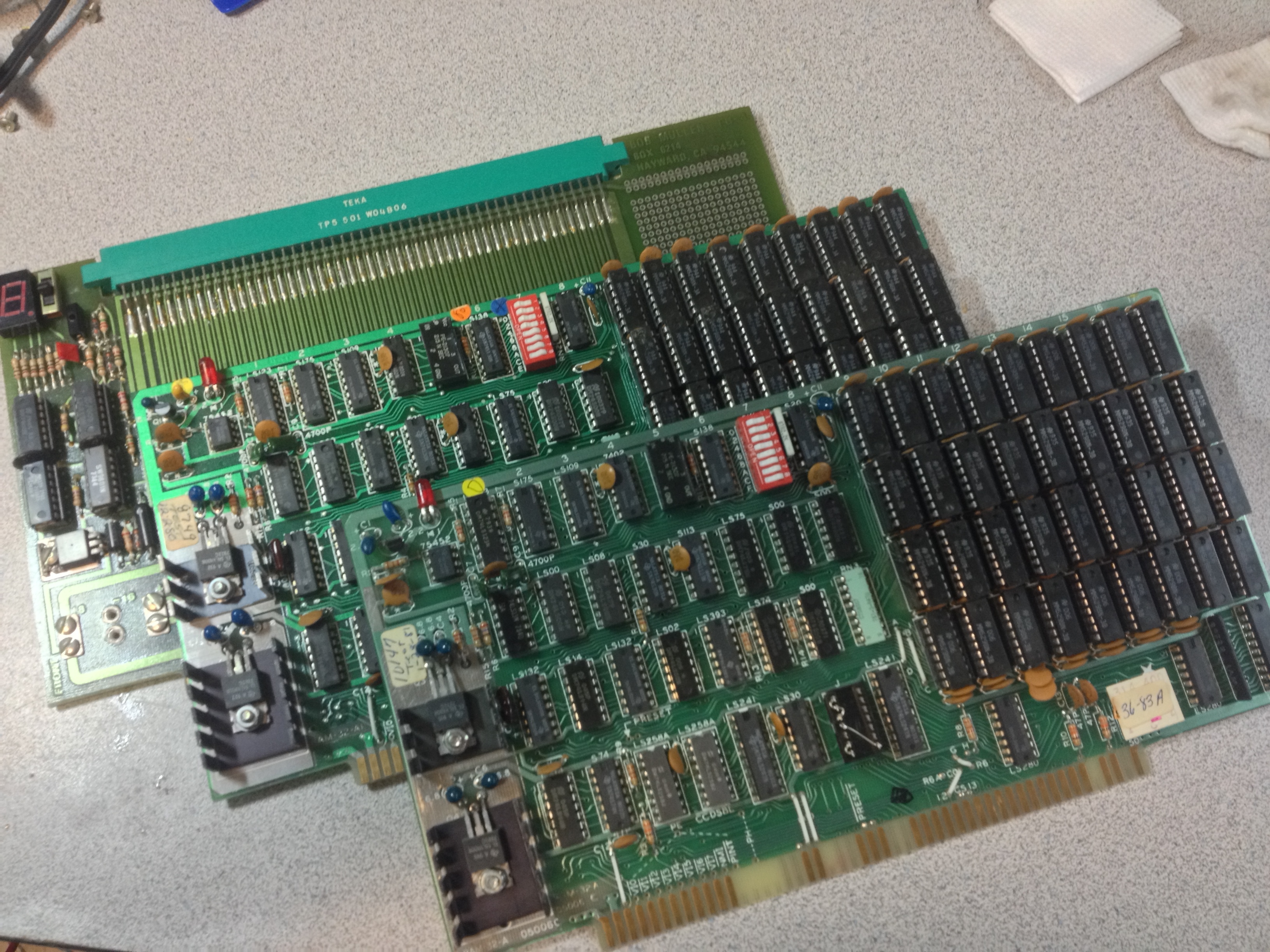
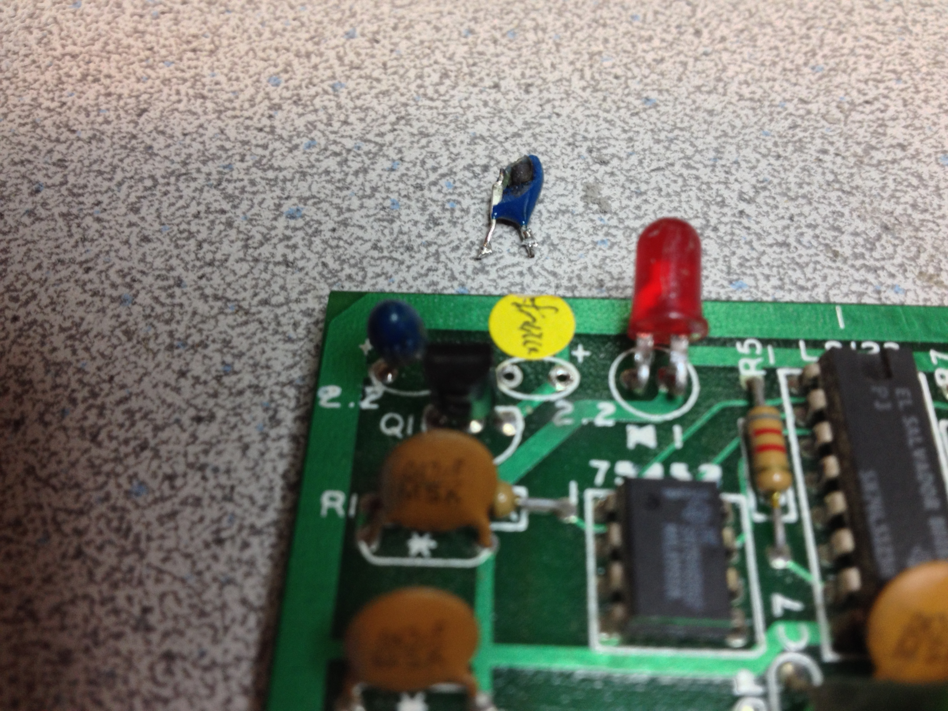
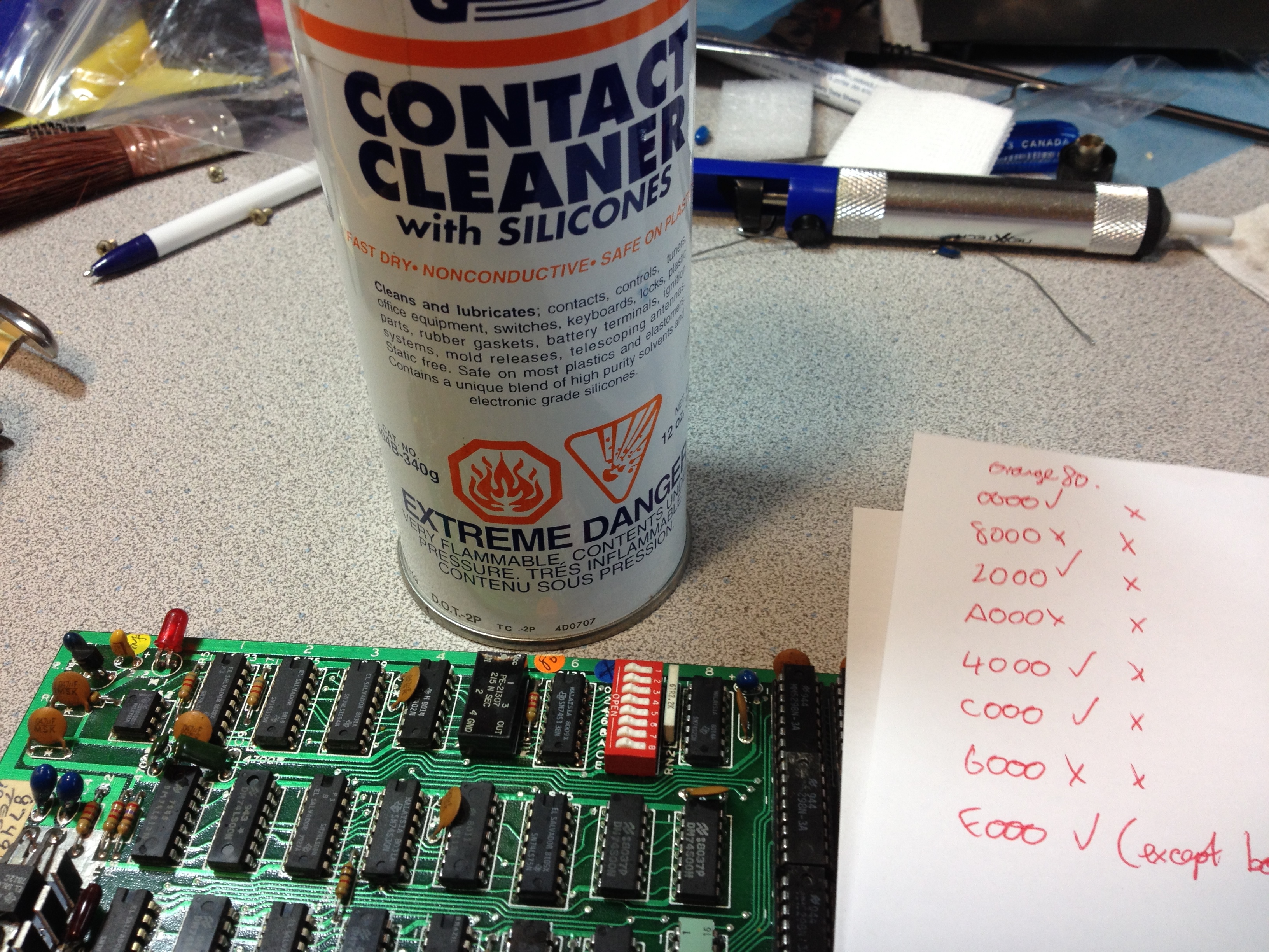
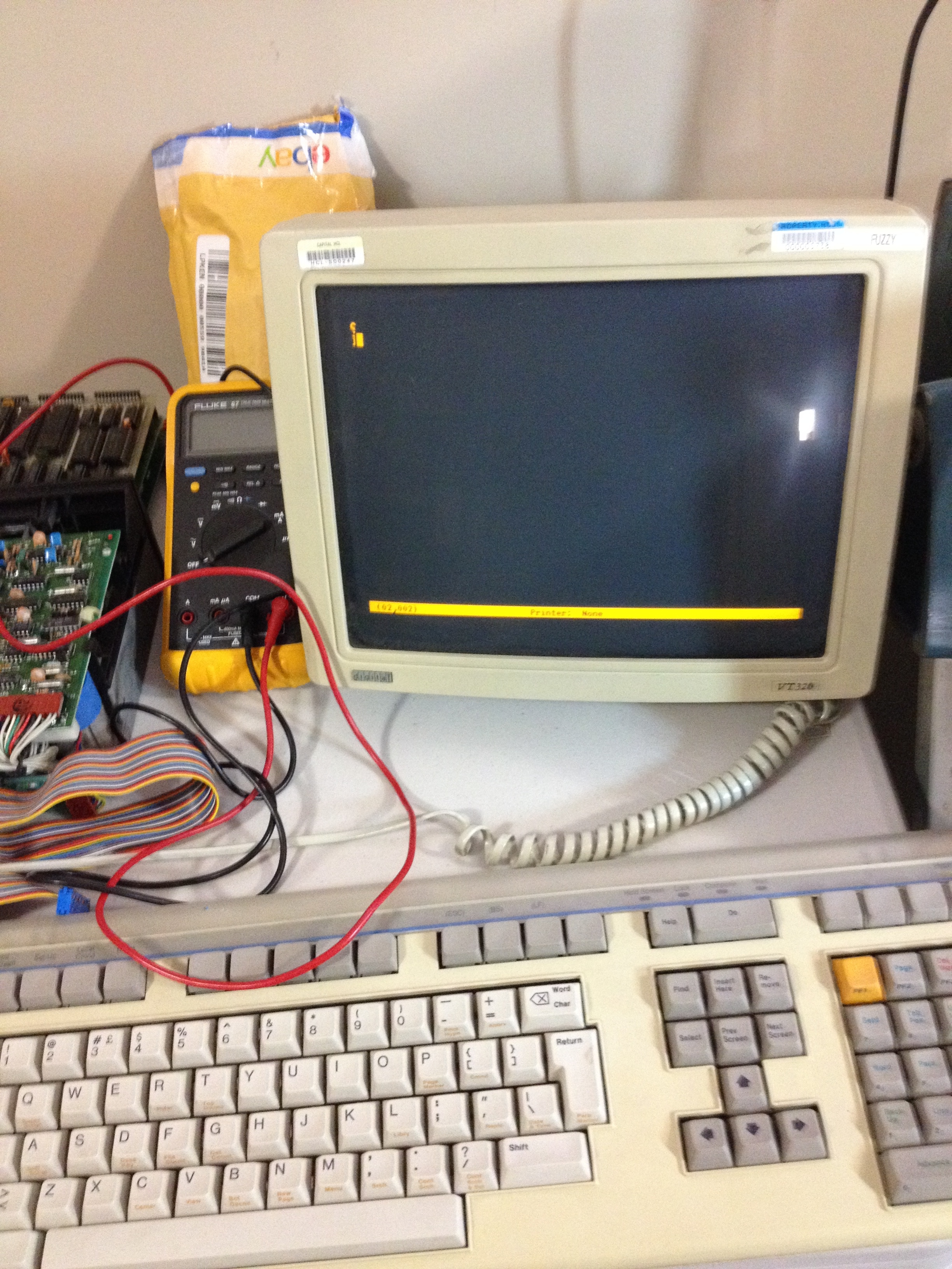
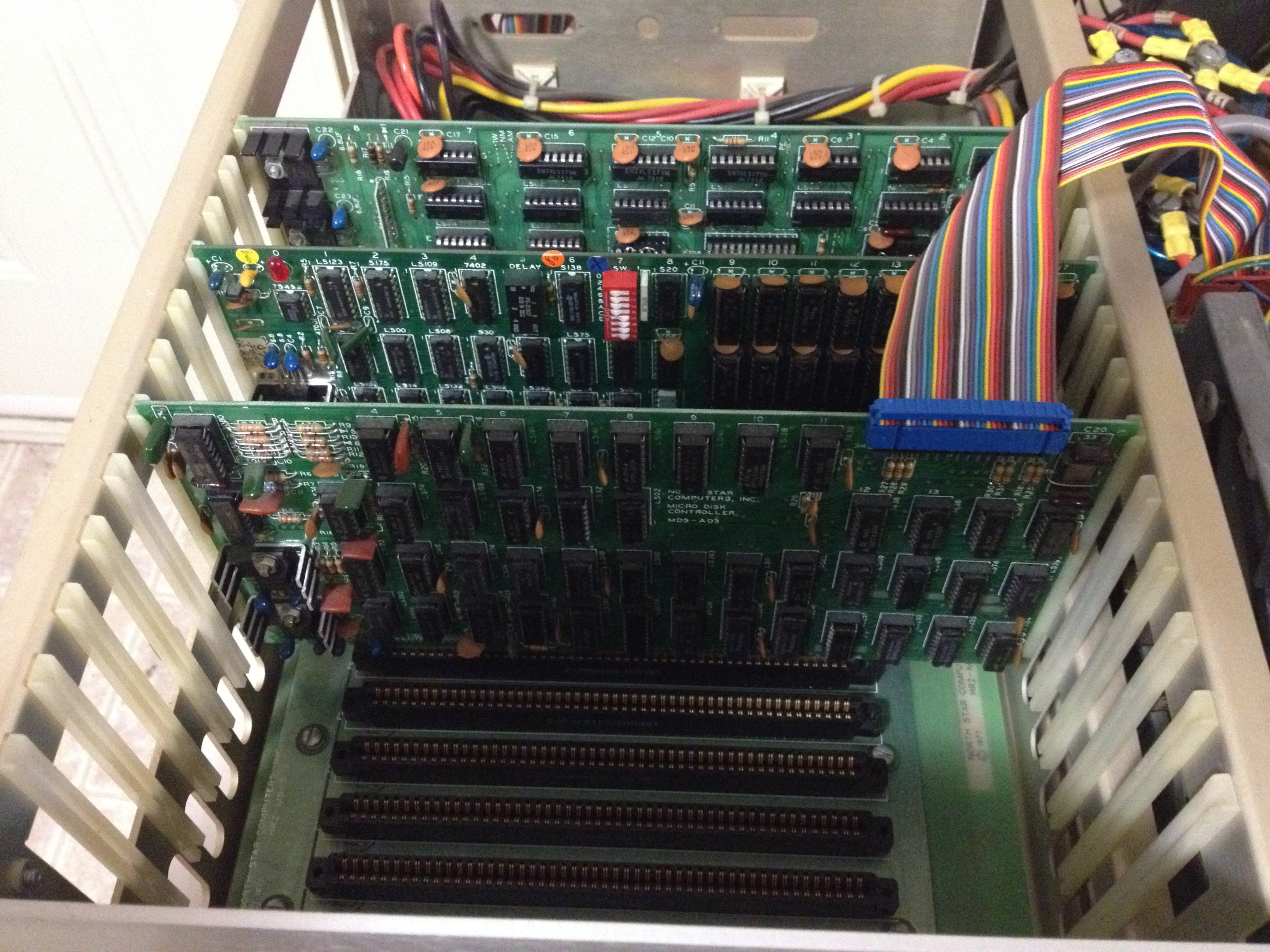
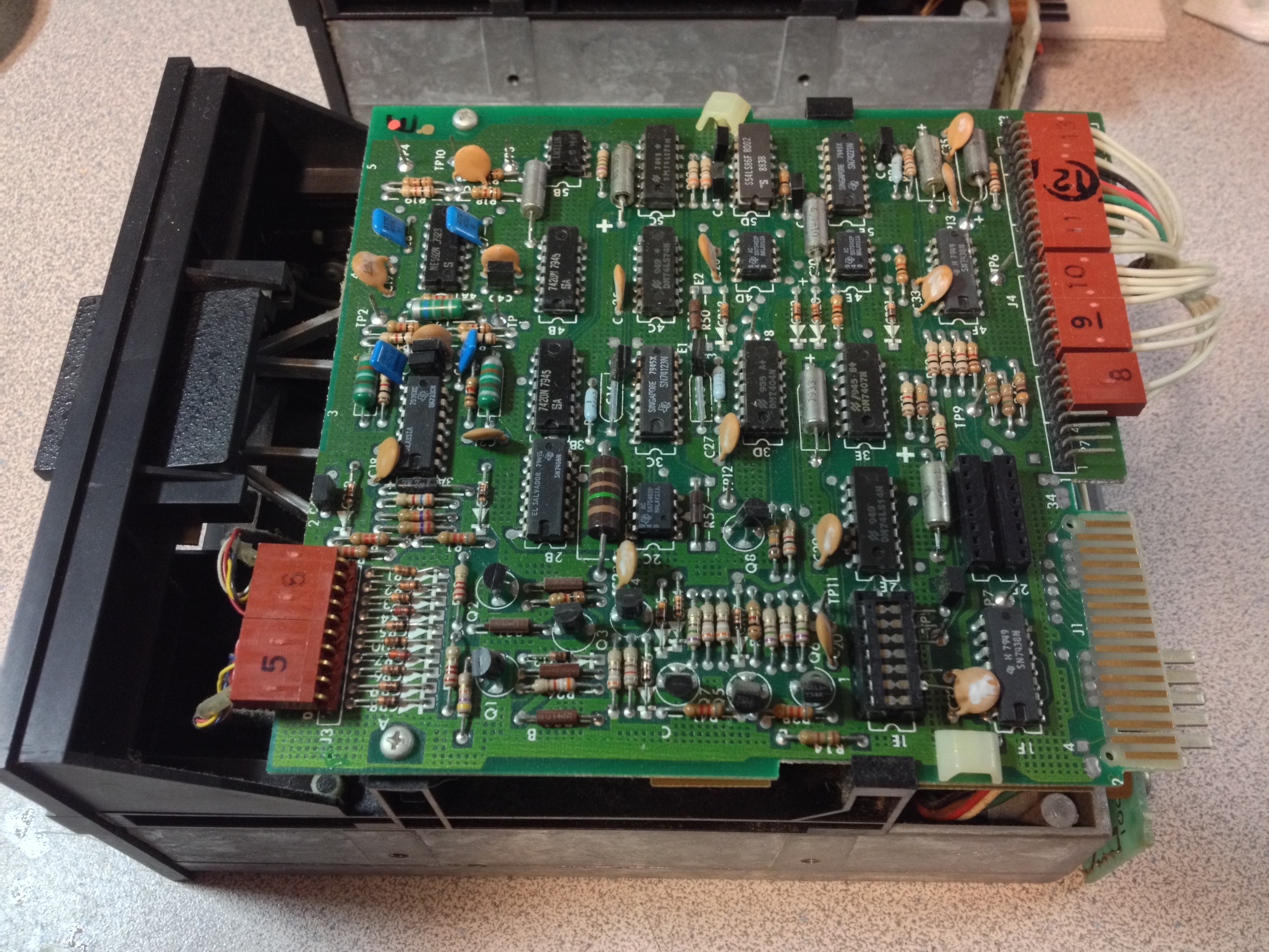
Electrically, all of the power rails were good. However, no memory banks were showing up no matter what dip switch settings I chose. If you recall, I had a problem with dirty dip switch contacts on the first memory board. Initially, I didn’t even suspect a bad switch on this one because there was nothing showing up. But I pulled out the meter anyway, and checked the dip switch. All 8 switches were either open or very high resistance. That’s why nothing was showing up – the machine thought I had disabled all of the banks. A few sprays with contact cleaner (still can’t find my non-lubricated can), and some vigorous switching, and now the contact resistance was down to almost zero.

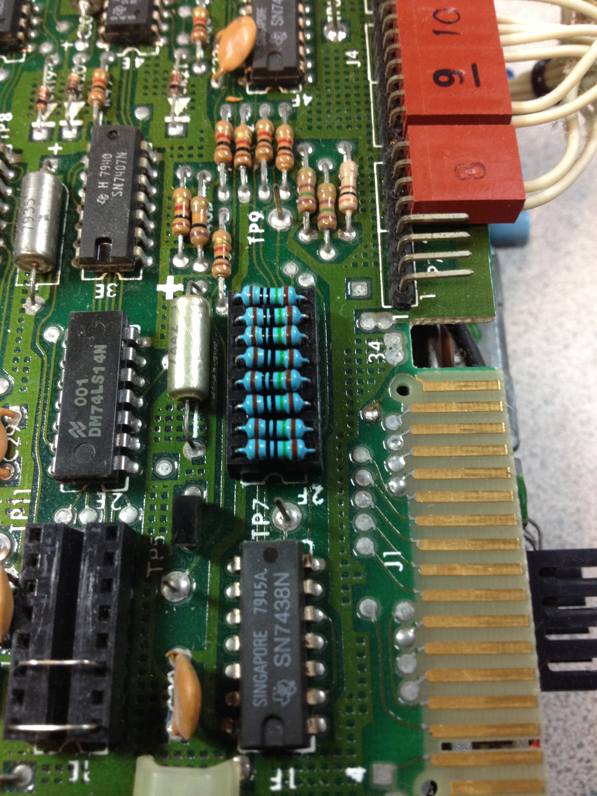
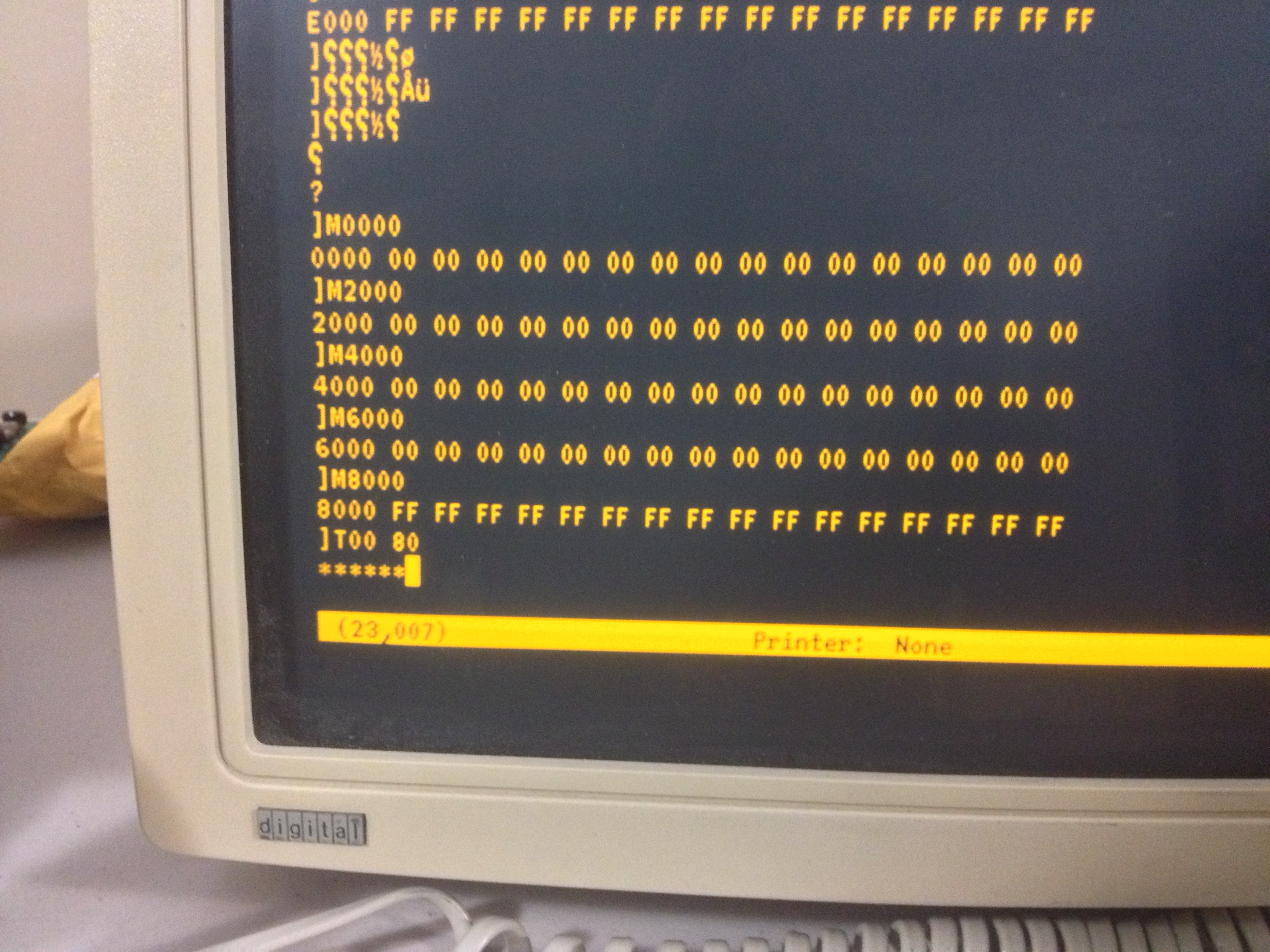
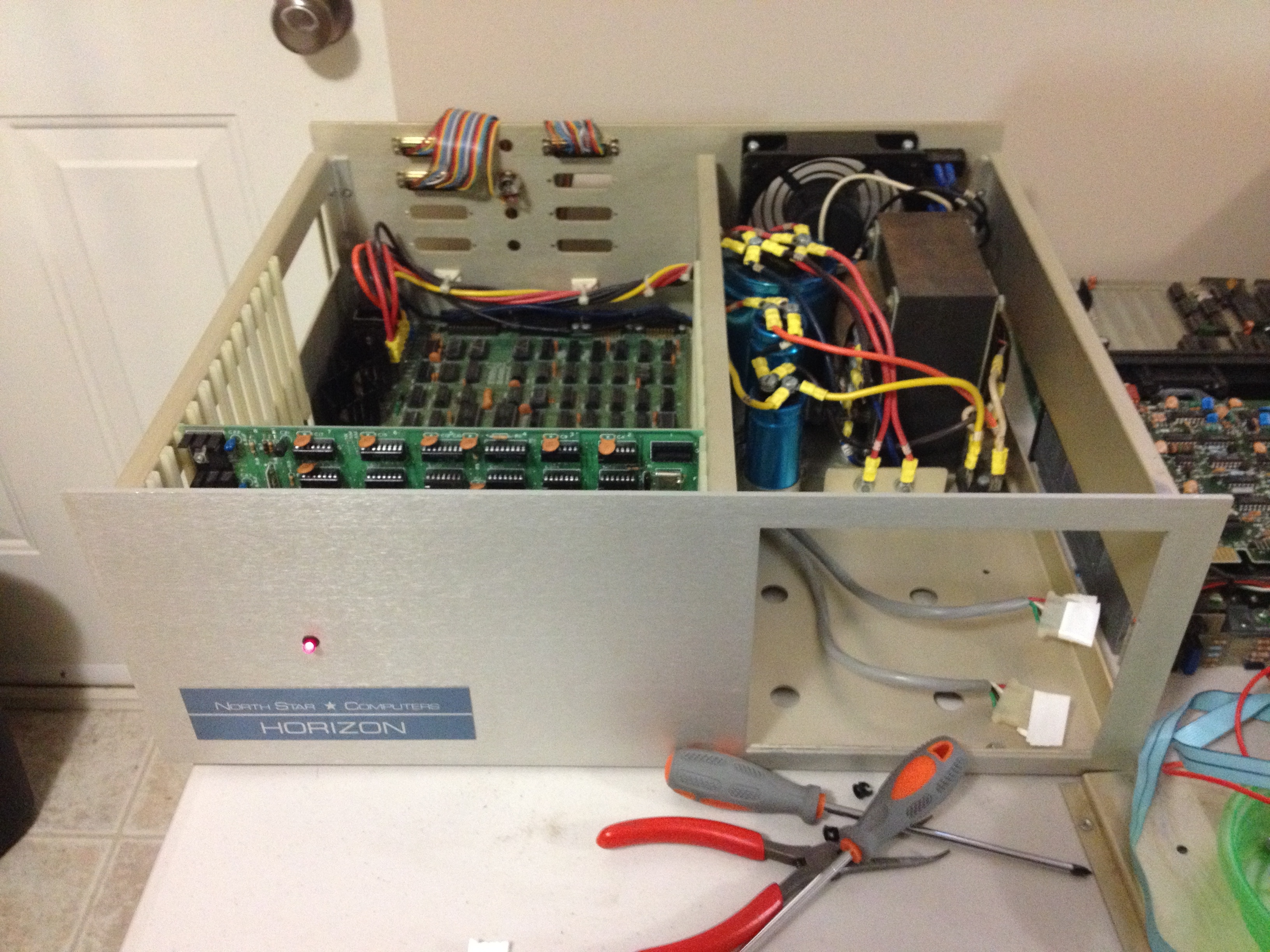
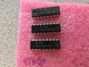
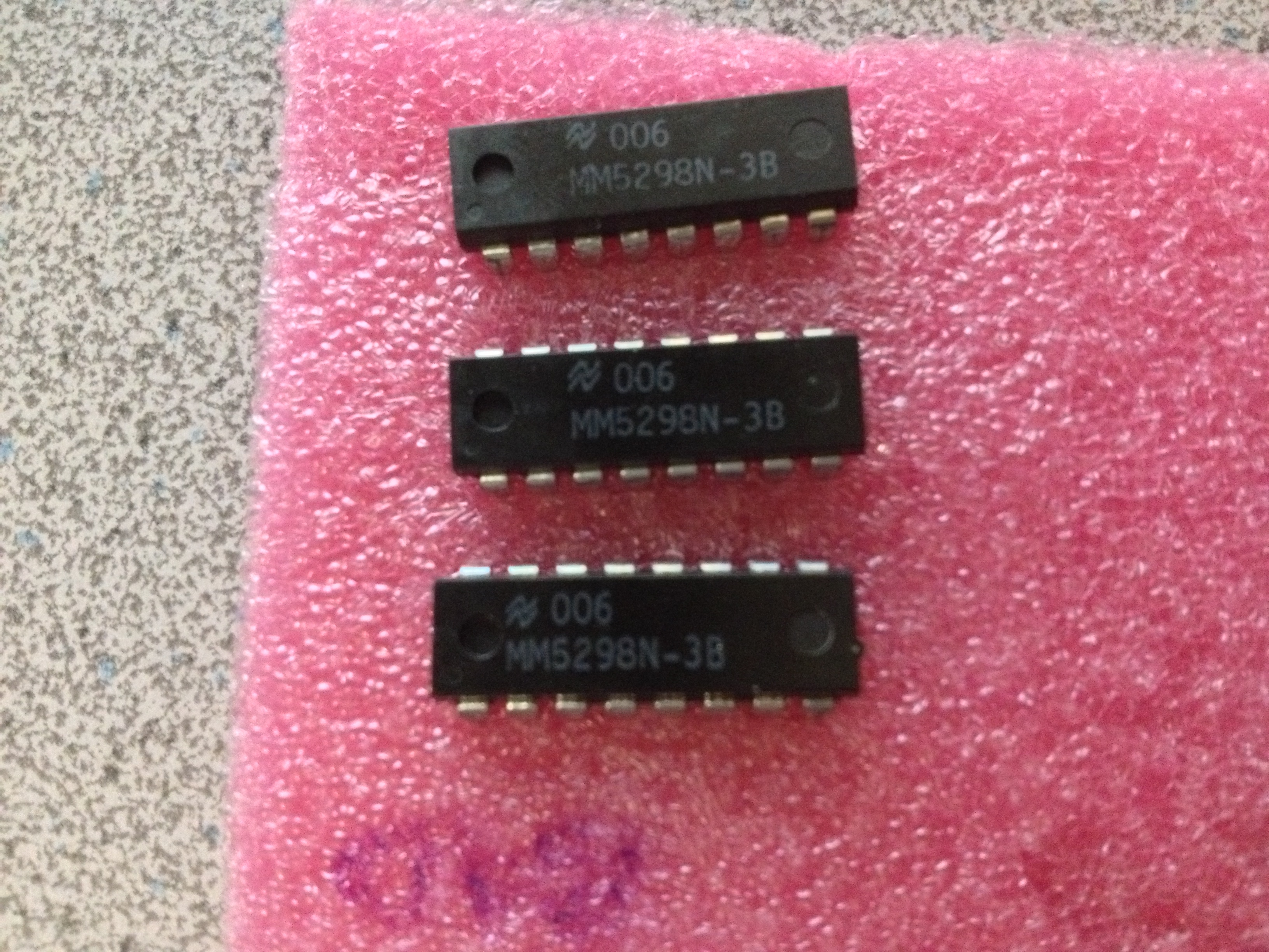
Back into the machine. Much better. Four banks detected. However, two of the banks failed a memory test. From the results of the memory test, I was able to determine that there was two stuck bits in one bank, and one stuck bit in the other bank. Without any spare DRAM chips, I decided to sacrifice one bank and make three good banks on the board. A visit to the schematic showed me which chip was which bit, and I was able to swap out a few chips. Another memory test, and I had 3 good banks for 24k of good RAM. I put both memory boards back in to the machine, and let it run a memory test for the full 56k of RAM overnight.

IMG_3032
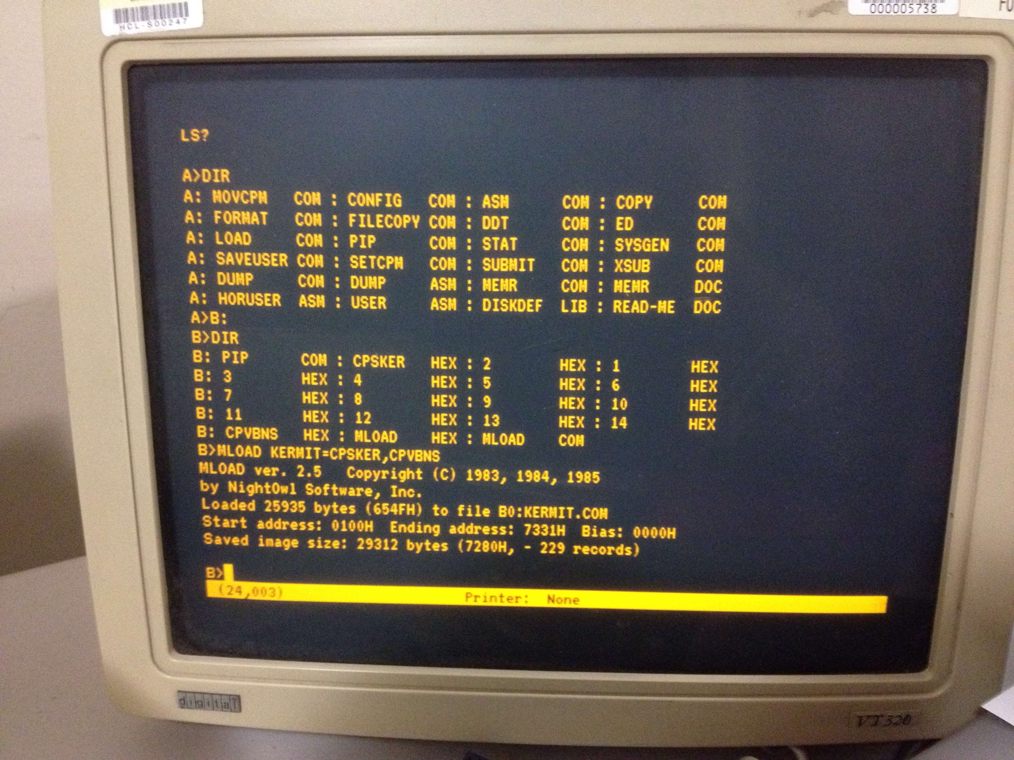
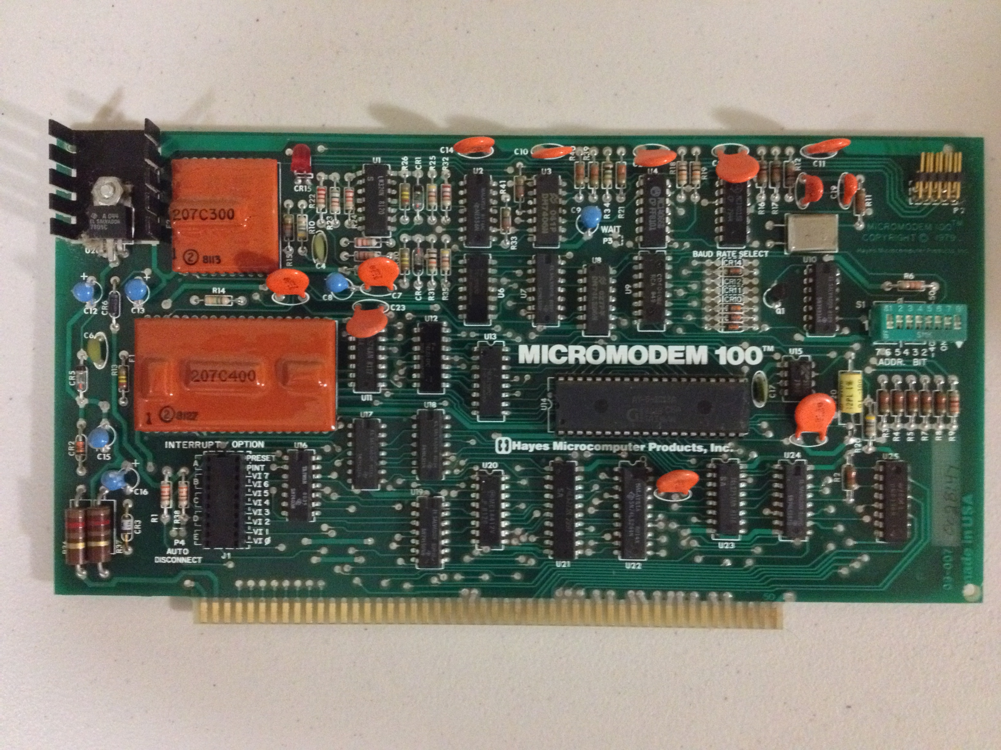
Now that I’ve got an almost-full compliment of RAM, I wondered if I could get KERMIT to build successfully. I still had the HEX files sitting on a data floppy, so I booted up and gave MLOAD a try. It worked! I was able to build a KERMIT binary. This is the point that I wasted several more hours trying to get KERMIT to actually transfer files, however. I was completely unsuccessful getting a file to move over, which was a bit disappointing. The whole reason I wanted KERMIT on the Horizon was to make moving binaries over to it much simpler. I had a binary for CLINK, a terminal program that works with the Hayes Micromodem 100, that I wanted to move over. It wasn’t going to happen with KERMIT, however.

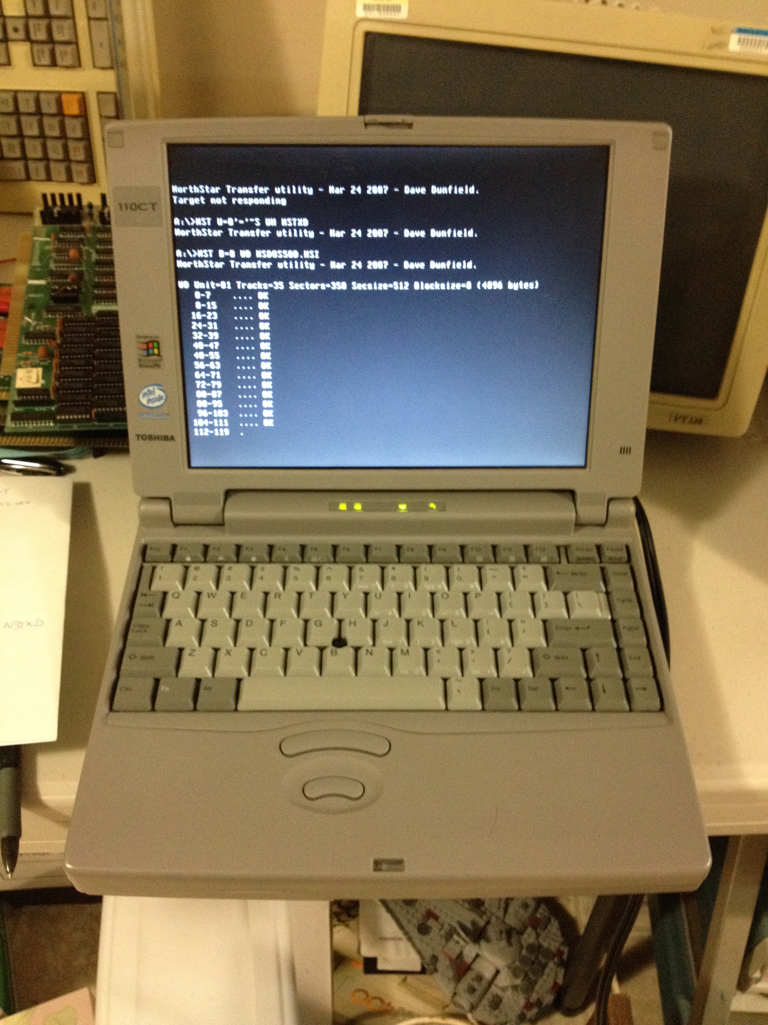
On the NorthStar, I was getting quite proficient using “PIP file.HEX=CON:” to copy a text file over the serial link. This does;t work with binaries because PIP is waiting for an end-of-file ^Z which may appear in the binary.

A different approach was needed. Maybe I could turn CLINK.COM into a HEX file first, then move it over, and convert it back once it was on the Horizon. What file formats was I working with? The CP/M .COM file format is very simple. It’s just pure binary data that gets loaded into memory location 0x0100 onwards. There’s no file headers or anything to worry about (at least in CP/M 2 – there is in CP/M 3). The .HEX file is just an Intel hex file – very common for burring EPROMs, etc. Could I find something that I could run on my Mac that could convert for me? Yes.

If you’re following along at home, you need the ‘srecord’ package that is available under brew. The syntax you need is:

srec_cat clink.com -binary -offset=0x0100 -o clink.hex -intel -address-length=2

Once I had clink.hex, I used the PIP trick to move it over, then used MLOAD to turn it back into a COM file.

IMG_2761
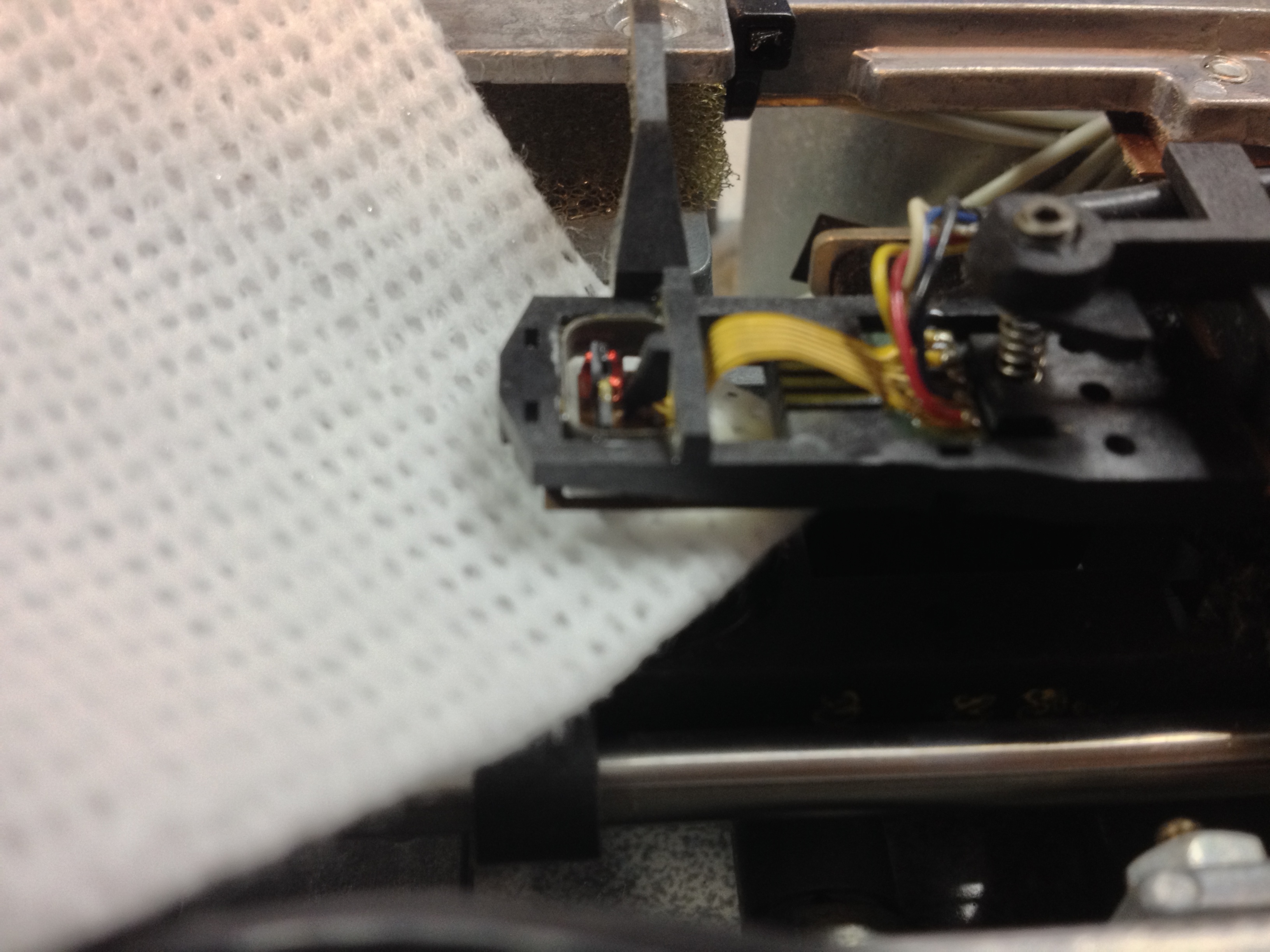
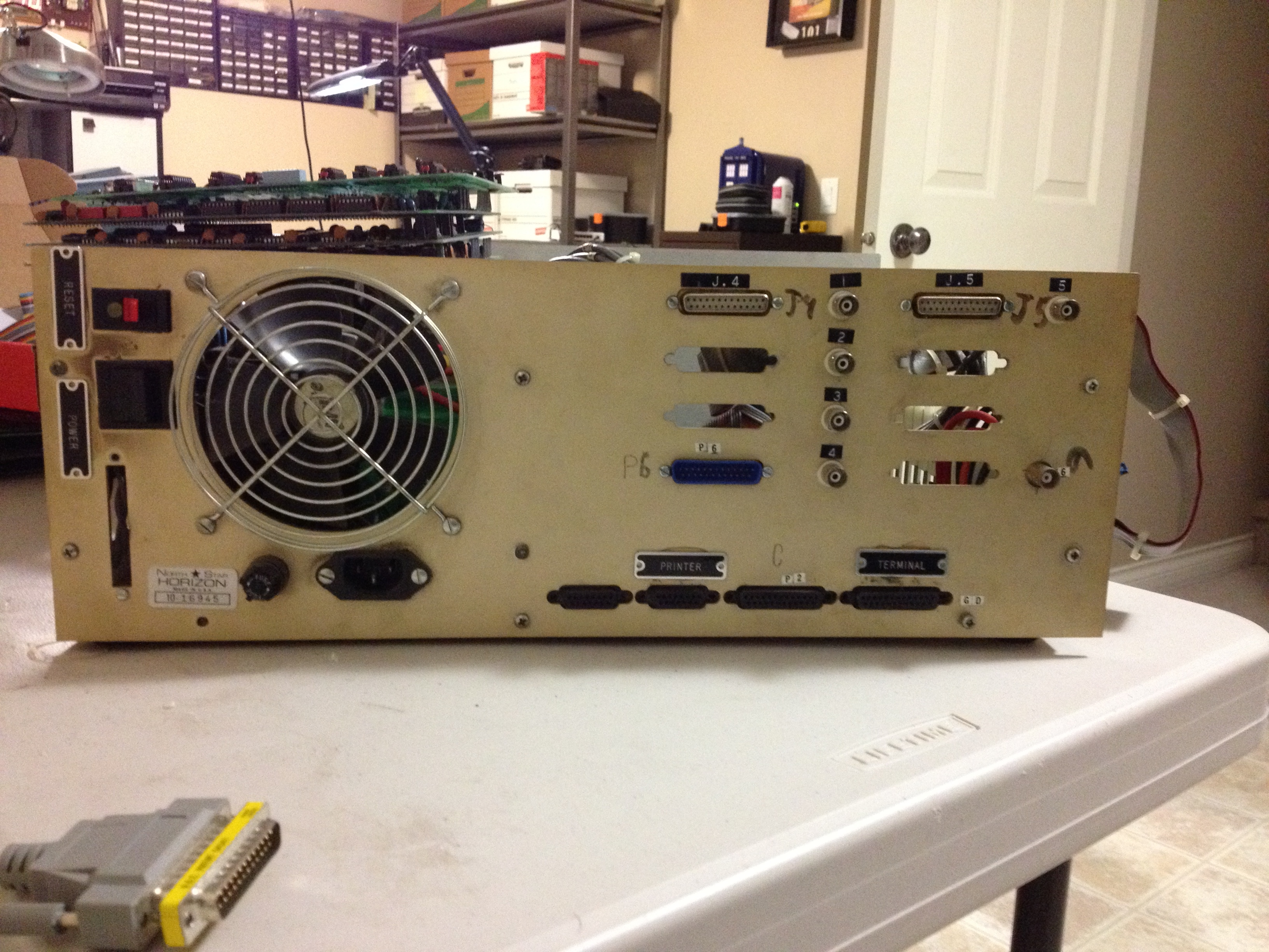
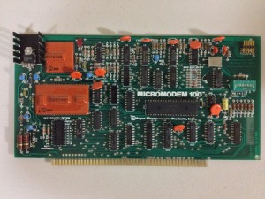
Now that I had the software, I needed to make sure the modem was working. Everything checked out electrically (250mA draw on the 5v rail), so I plugged it in to the backplane. A quick test with CLINK made the modem click away the number I entered (pulse dialling). A quick rummage around found a telephone extension cable, and I plugged the modem in to the phone line.

IMG_3045
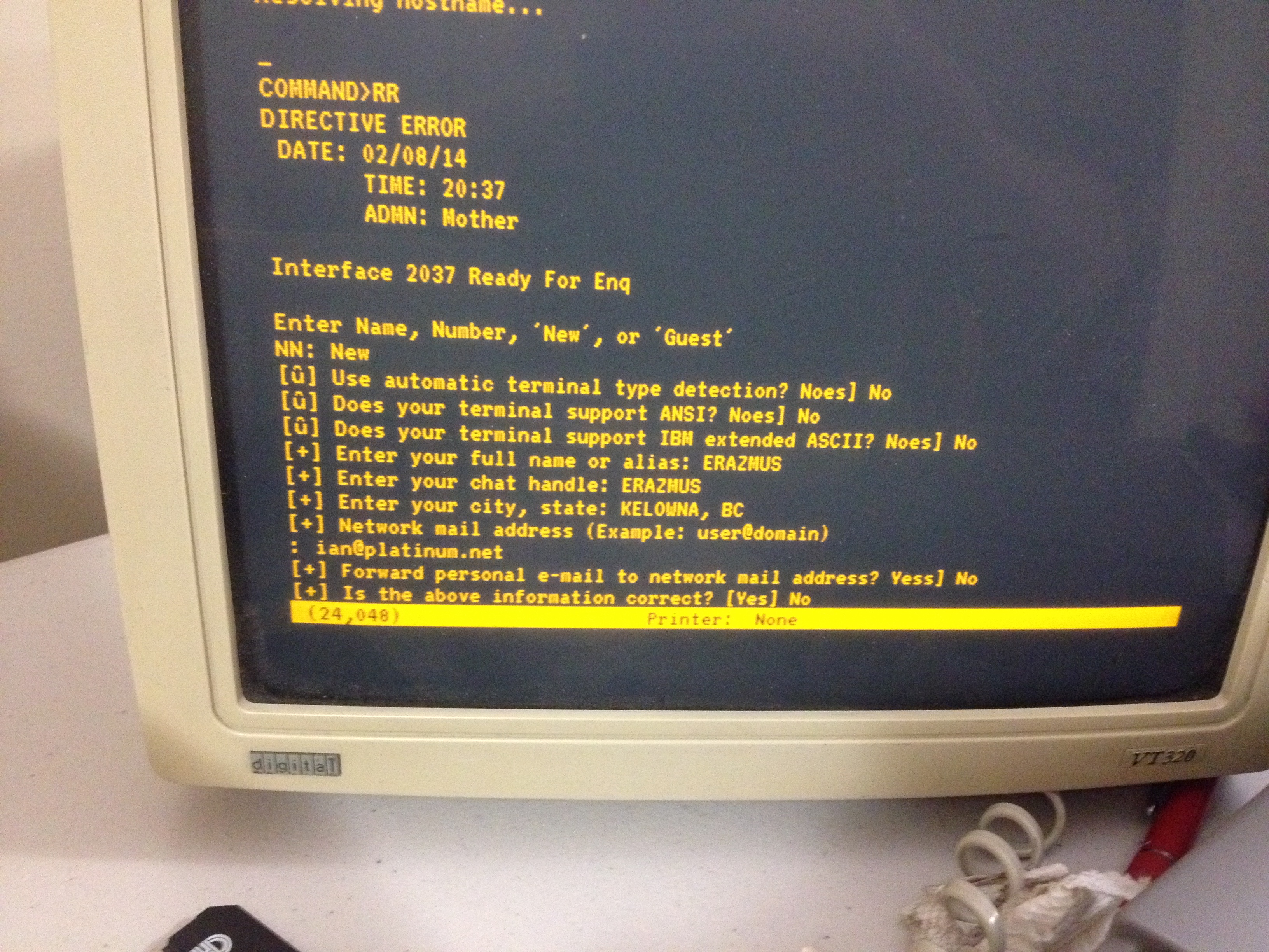
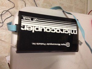
All hooked up. Can it make a call? For some reason, there aren’t that many BBSs around any more 🙂  @retrocosm was kind enough to furnish me with the (UK) phone number to his BBS that was born during his 2011 RetroChallenge entry.

8 data bits, no parity, 1 stop bit, 300 baud. Time to call. No speaker on this modem, so I don’t get to hear the heart-warming sound of modems connecting, but a few seconds later, and I’m connected!

IMG_3051
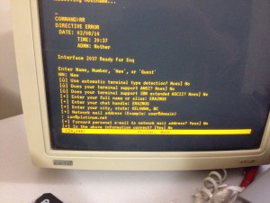
Ending RetroChallenge by dialling into a BBS created for a RetroChallenge using my RetroChallenge entry was somehow very satisfying. I’m glad I spent the extra couple of days to tie up the loose ends.
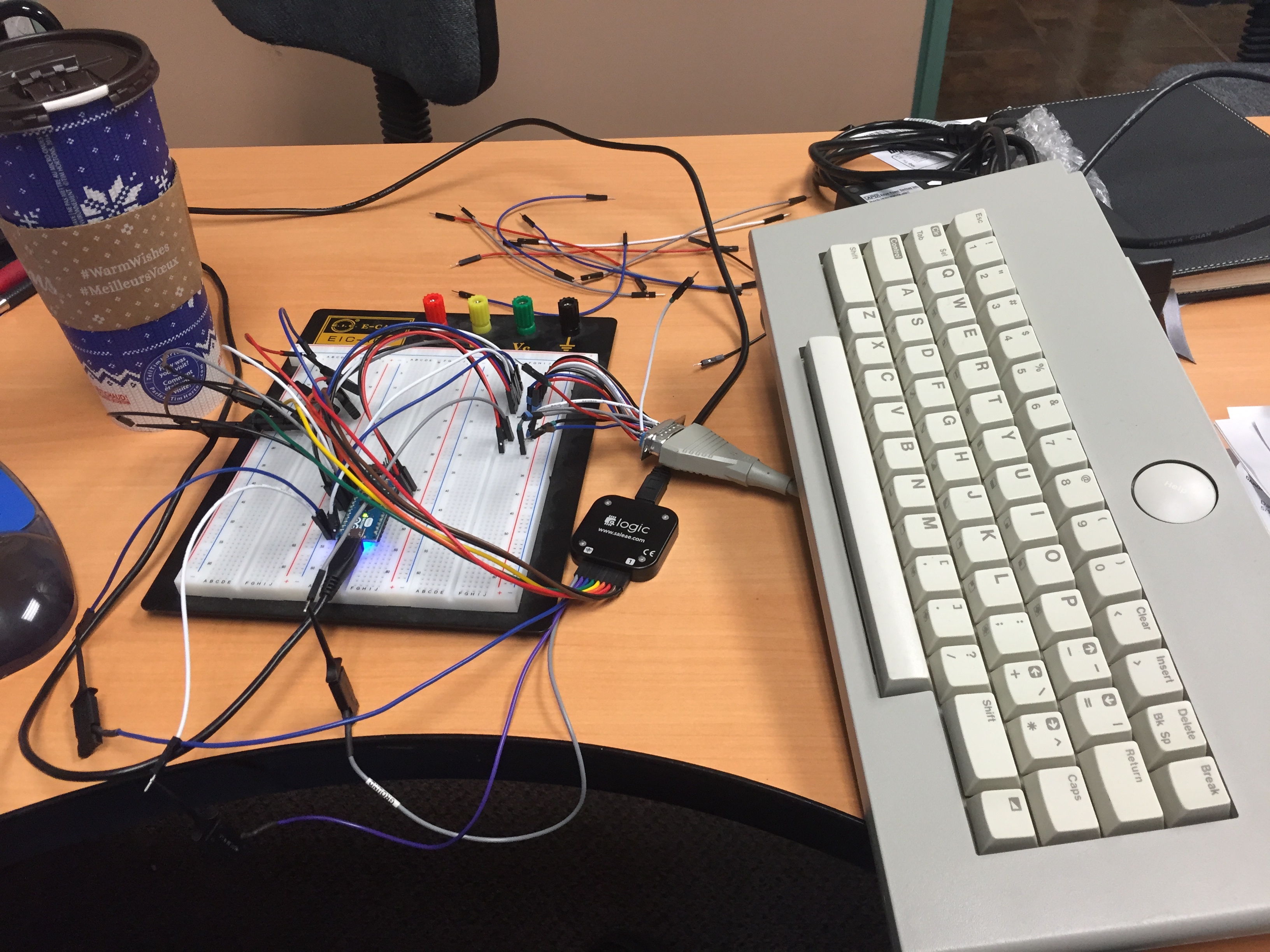
Final Retrochallenge 2014 Post

IMG_3029That’s it for Retrochallenge 2014. I didn’t get everything done that I wanted to, but I’m still very happy. I finally got to scratch an itch that I’ve had since 1977 – I now own my very own S100 machine. I would pour over the latest issue of Byte magazine and drool over the latest S100 board that had been released. There was no way I’d ever be able to afford one of these amazing machines, so my computing itch had to be scratched by my Compukit UK101.

So what did I accomplish during the month of July? I was able to fully disassemble, test, and restore the electronics of a NorthStar Horizon. I managed to get a working boot disk on media that is almost unobtanium. The most iconic part of this machine – the wooden case – still needs some love. I still have one broken memory card, which I am going to use as the reason for not getting any further. I have spent the last week trying to get Kermit-80 transferred and running. After running into buffer overrun errors while trying to transfer the big HEX file, I broke it up into smaller chunks, which transferred successfully. I was able to stitch the pieces back together using PIP. But no matter how many times I tried, I was unable to get LOAD or MLOAD to confer the HEX file to a binary. Tonight I started looking at the hex file a bit closer. From my rudimentary knowledge of Intel HEX files, it looks like the last few bytes are at address 0x7070. That’s 28k – real close to my 32k ceiling. No idea how much RAM CP/M needs, but I doubt that I’ve got enough memory to have CP/M, MLOAD, and the hex file all in memory at once.

IMG_2761What’s next? I fully intend to get the second 32k memory running – I have a bus extender board and plenty of appropriately-aged test gear. Once I’m back to a full compliment of RAM, I really want to get the Hayes Micromodem 100 running. Watching Tezza’s Retrochallenge demo code bring up text on the screen at teletype speeds really brought back memories of BBSs at 300 baud.

I’ve had loads of fun. I’ve really enjoyed watching all of the other entries, and some of them have given me some ideas for the Retrochallenge Winter Warmup… Bring it on!

Booting CP/M

IMG_2967One last board left to make a basic working machine. The disk controller board was completely socketed, so I removed each chip one at a time and used the glass pen to clean corrosion off of the pins. All capacitors tested okay, and a current-limited power-up proved successful. I placed the board in my machine, and I was able to see the boot ROM at address E800 visible  from my monitor. Then it was time to plug the floppy drive cable in. After reading online about warnings of destroying floppy drives and controller cards by plugging in the cable backwards, I spent a bit of time double-checking that I was plugging the cable in correctly. It was a good thing I did double-check – the pin 1 identifier on the connector was wrong! The ribbon was correct – the brown wire was pin 1.

Once plugged in, I powered up, and jumped to the boot code at E800. Success! Drive 1 started to spin and the LED lit up! Now came the difficult part. Any NorthStar Horizon collector will tell you that the hardest part about bootstrapping the machine is the fact that the floppy disks are hard sectored. It is highly unlikely that you’ll haver any other machine around that can write these disks, so creating a boot disk is a challenge.

Thankfully, Dave Dunfield has done the hard work by making a neat bootstrap stub that talks to a DOS utility for reading and writing NorthStar disk images. This is the whole reason I needed to install the monitor ROM in the first place – the monitor ROM is the absolute minimum needed to get code in to the machine. Dave provides instructions for getting his DOS utility to pretend to type in his bootstrap stub into the monitor prompt.

I spent way too much time trying to get various virtual machines to run the DOS program, but with no success.  To be fair, Dave does warn users that anything newer than Windows 98 will have problems, and I can confirm this 🙂

IMG_2980I ended up digging out an old Toshiba Satellite 110CT laptop (with broken hard drive and dead battery). Of course I had no boot floppies for this machine, so I had to pick up a USB 3.5″ floppy drive for my Mac to write a DOS 6.22 disk so that I could boot the DOS laptop so I could use it to boot the Horizon!

The first disk I was able to make with this setup was NorthStar DOS. A quick toggle of the reset switch, and my NorthStar booted NorthStar DOS! A few minutes of playing confirmed my suspicions of NorthStar DOS – it’s weird.

IMG_2987For 1975, I’m sure it was quite powerful, but having to allocate sector ranges for each file is a bit tedious. I played with it long enough for me to comfortably say that I’ve tried it and it’s not my cup of tea.

The next logical step was to try to get CP/M up and running. Knowing that I had double-sided double-density drives (called Quad Density in NorthStar lingo) I tried to write a CP/M disk that was in QD. This failed half way through every time I tried it. I was unable to get Dave’s software to write a double sided disk no matter what I tried. A bit more digging, and I found a single-sided CP/M image. This disk wrote successfully, and I was greeted with the friendly A> prompt after rebooting.

IMG_3017I configured CP/M to recognize double sided double density drives, and I was able to successfully format, write and read double sided disks. Thankfully it’s just Dave’s software and not a problem with my double sided drives.

As can be seen from the screenshot, there’s precious little utilities included on this disk, but apparently I’m supposed to be able to use PIP to read in a HEX file over the serial port, then use LOAD to write it to memory, which I can then save to disk. I will need to do this to get Kermit-80 in to the machine, which I can then use to get anything else in there that I need. Only a couple more days left in the Retro Challenge. Am I going to be able to get the modem running in time? Doubtful…

Floppy Drive Cleaning

IMG_2937My NorthStar Horizon came with two Tandon TM100 floppy drives. As I mentioned previously, these were jumpered for drives 3 and 4. I don’t have any other drives to plug in to this system, so I need to re-jumper these for drives 1 and 2.

Even though the service manual is easily downloadable from the net, I don’t have an alignment floppy disk, so I needed to be careful disassembling and cleaning those drives. I took great care not to take apart any assembly that would alter the alignment of the heads or the track 0 sensor. This limited me to basically removing the circuit board to gain access to the mechanism below.

IMG_2821
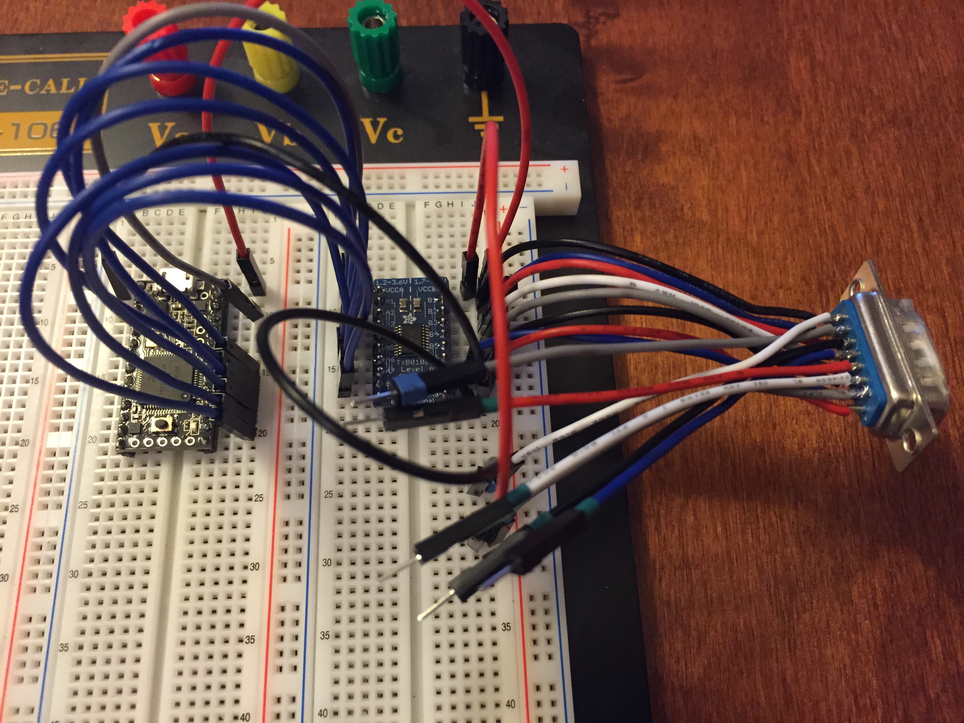
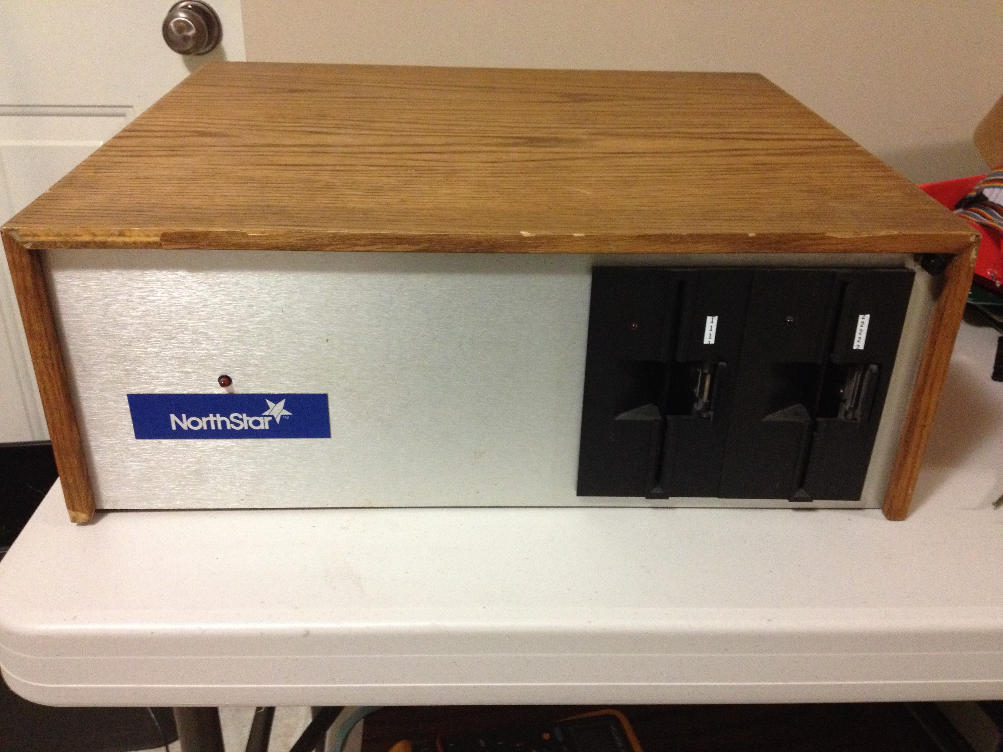
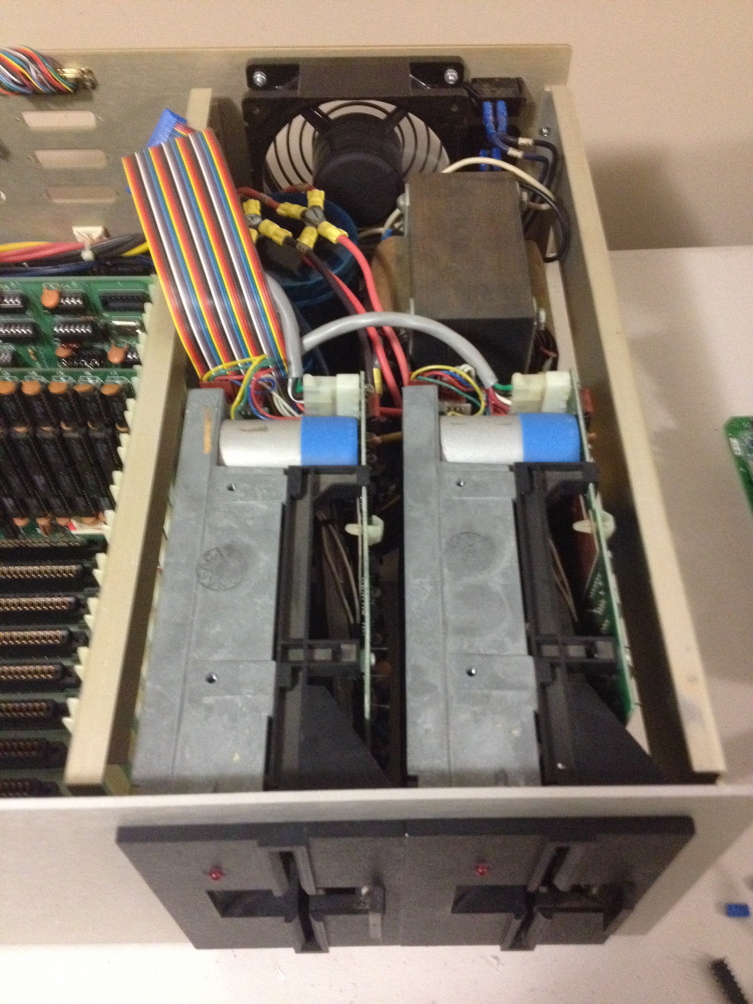
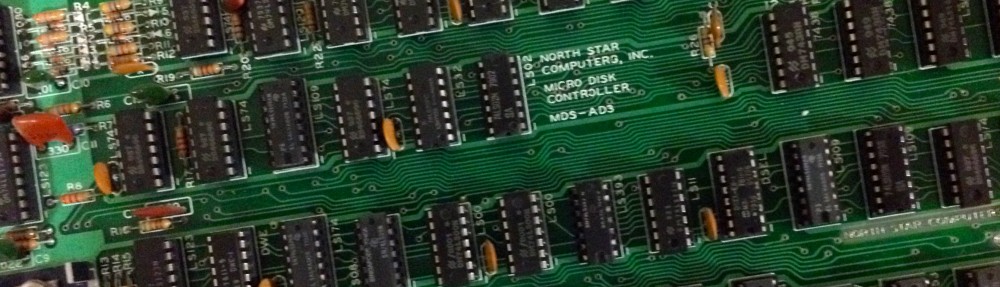
The floppy drives were in remarkably good condition. The belts are snug, with no signs of slipping. The circuit board was in good shape. I removed the strange ID4 add-on wire (mentioned in an earlier post) and returned the jumpers to ID1 and 2. I had no terminator resistor pack, which needs to be installed in the last physical drive in the chain, so I had to manufacture one. The service manual mentioned a value of 150Ω so I grabbed some 1/4W resistors, cut them to length, and inserted them into the terminator socket. The on-board electrolytic capacitors were checked for tolerance and ESR, and all passed. I couldn’t locate any tantalum capacitors (good).

IMG_2945The drive rails were in good condition, but needed a clean and some lubrication. The heads had a bit of oxide build-up, so had to be cleaned. I placed a lint-free wipe soaked in isopropyl alcohol in between the two heads, and closed the mechanism so the heads pushed up against the wipe. The bottom head is a nice solidly mounted head that I’m used to seeing in 5 1/4″ drives, however the top head was a very delicate unframed head held in place with a fragile-looking spring mechanism. Any lateral force (such as pulling the wipe sideways) would possibly bend this mounting mechanism, so I had to be careful. Several open-close motions cleaned the oxide buildup from the heads quite well.

IMG_2948After re-assembling the drives, I powered them up using a current-limited supply, to make sure there were no shorts. Everything looked good, so it was time to mount them back in the case. It took me a little while to determine NorthStar’s factory placement of drive 1 and 2, but after some digging, I was able to find out that drive 1 was the right-most drive (not what I would have guessed, but I’m trying to be authentic).

IMG_2955For such a spacious case, the floppy drives are quite a squeeze, and it was a careful dance to get the drives partially in place, then the power and data cables connected, then sliding the drives all the way in. I learned the hard way that this procedure had to be performed with both drives at the same time, after many attempts at doing the drives one at a time.

The machine is really starting to look like a real computer now. Once I get the floppy controller back in, I should be able to attempt a boot!

My Memory – It’s All Coming Back To Me Now!

IMG_2935As I mentioned in my last update, I was without any NorthStar RAM for this machine. I spent several hours trying to get the Dynabyte 64k board running, but didn’t get much success. Unable to find any documentation for the board online, I had to try to reverse engineer the bank switching scheme used. I managed to figure it out, and was able to use my monitor to switch banks on and off, I was unable to get the RAM to actually work. I could read just fine, but writing always resulted in the value FF being deposited.

I was starting to think that this might be the end of my Retrochallenge (what use is a machine with no RAM?), so I put out a plea looking for S100 RAM boards in a couple of retro mailing lists. I received a couple of offers go help, and incredibly I was able to locate not one but TWO NorthStar memory boards right here in my small home town of Kelowna (population approx. 120,000). He even threw in an S100 extender board!

IMG_2919These memory boards – part number RAM-32-A – were much better to work with because of the ready availability of documentation. The first steps were familiar to me now – test all of the tantalum capacitors for shorts. One of the boards had a tantalum that had already experienced a catastrophic failure – half of it was missing. I dropped in a replacement, then tested the power rails by bringing each one up on a current-limited supply. Both boards passed these tests, so now it was time to test each board in the Horizon.

IMG_2927One board failed completely – the red LED didn’t even light up. However, the second board showed very encouraging signs of life. Using the documentation to enable each 8k bank one at a time, I was able to deduce that all banks were working, however not all banks worked in both bank locations (each bank can appear in one of two locations, or be switched off completely). I suspected the DIP switches as the likely culprit, so I tested the switches with my meter – yup, several switches had a very high resistance or complete open circuit. A quick spray of contact cleaner and some vigorous switching should clean those up. I could only locate my lubricated contact cleaner, which is not ideal for this application (it’s more useful for things like relay contacts), but because my regular contact cleaner was MIA, this would have to do.

IMG_2930Sure enough, this fixed it! 32k of beautiful error-free RAM. My monitor ROM has a memory testing function, so I left this running for several hours, and not a single memory fault! I will save the debugging of the second board until later, but for now I have a respectable 32k to play with. I think the next step is to get the floppy drives going, and eventually get to the point of writing a boot disk.

First Light!

This weekend I’m spending at the lake, so I’m nowhere near the Horizon (849km away according to Google), but I had a small flurry of success just before I left, and I have a few minutes relaxing by the bonfire with a drink in hand, so I might as well grab the photos from my phone and bring my project up to date.

IMG_2889Now that I have a power supply, motherboard, and CPU board with monitor ROM, I have enough pieces to see if I can get some signs of life out of the machine.

I pulled out my trusty VT220 and hooked it up. At this point, all I have in the backplane is the CPU board with the boot PROM. There is no RAM yet, but according to the documentation for the monitor ROM, it operates with no need for RAM – which is very handy for testing. My motherboard is strapped for 9600 baud, so I set the terminal to the same speed, and I power everything on.

IMG_2888A prompt! Well, not right away – I had to exchange my serial cable for a null-modem cable, but then – a prompt! The ‘]’ symbol is the appropriate prompt for this monitor. No fancy sign-on bender (what was I expecting for a 1K monitor?)

I can examine memory (everything is FF except for the 1K of monitor ROM), and depositing doesn’t change anything, but it’s working! What does this success tell me? It tells me that the serial port is working (and if the serial port is working, reading and writing to I/O ports is also working). The address and data busses are also working. This makes me happy!

As I have mentioned previously, the biggest challenge I’m going to face with this project is the lack of any NorthStar memory boards. The machine didn’t come with any, but I did acquire a Dynabyte 64k memory board of unknown operational status. I made a request last week on some mailing lists, and amazingly I was able to find someone willing to part with two 32k Northstar memory boards – and the amazing part was they were located in Kelowna! I grabbed them (and a nice S100 extender card) just before I left for the lake, so I can’t wait to get back and test them out!

IMG_2923Now back to the task at hand…