Missing Power Rail

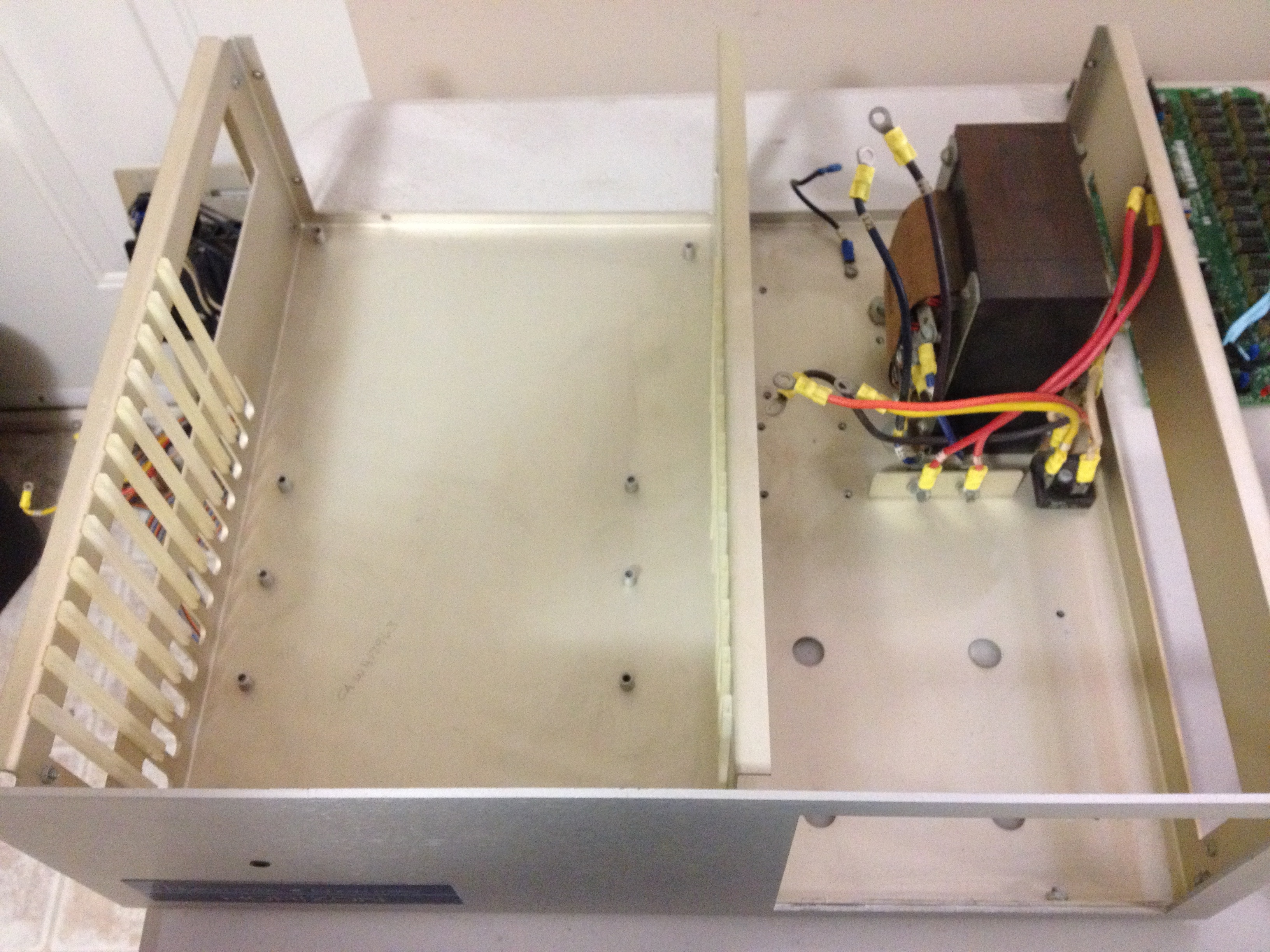
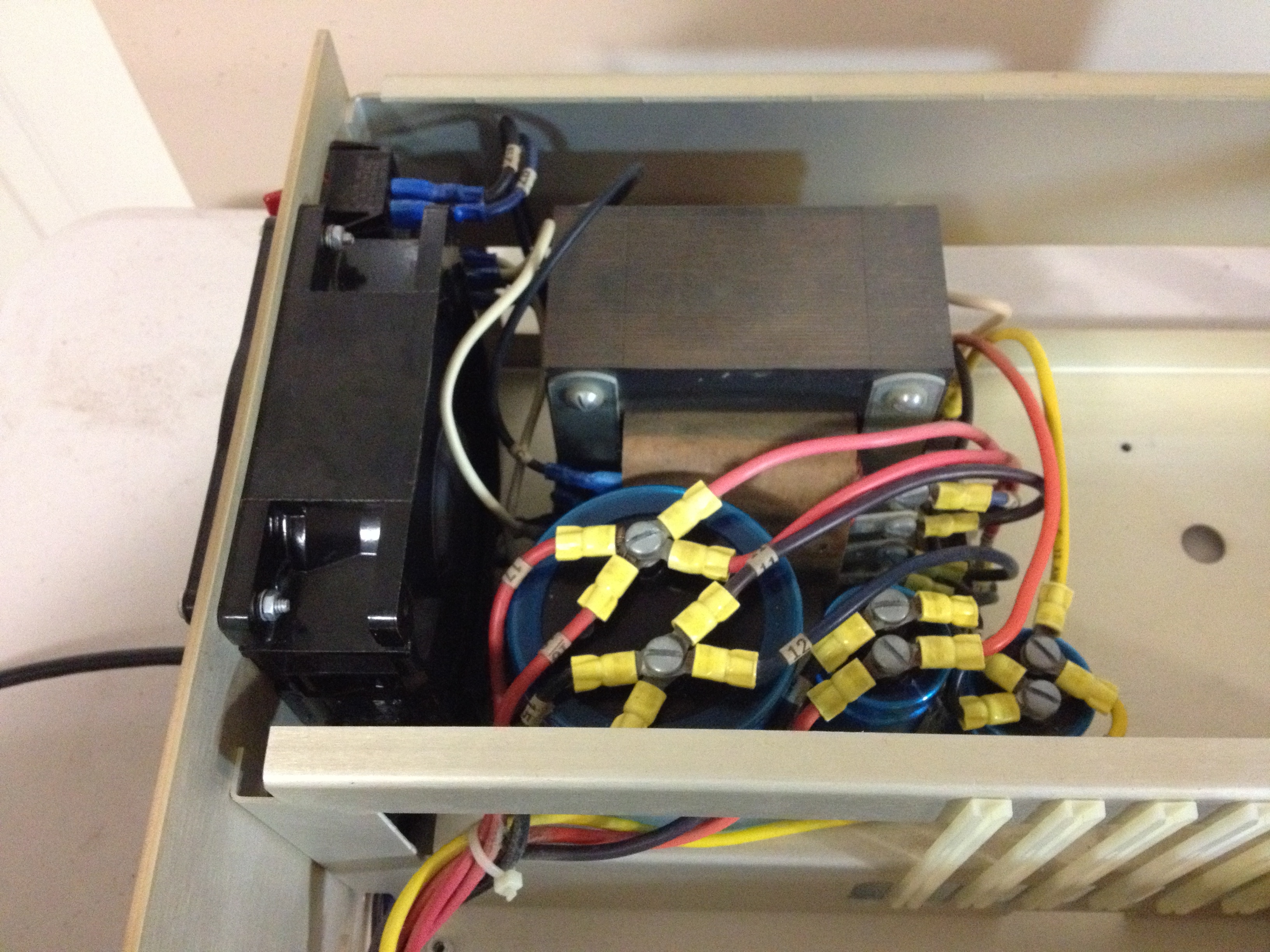
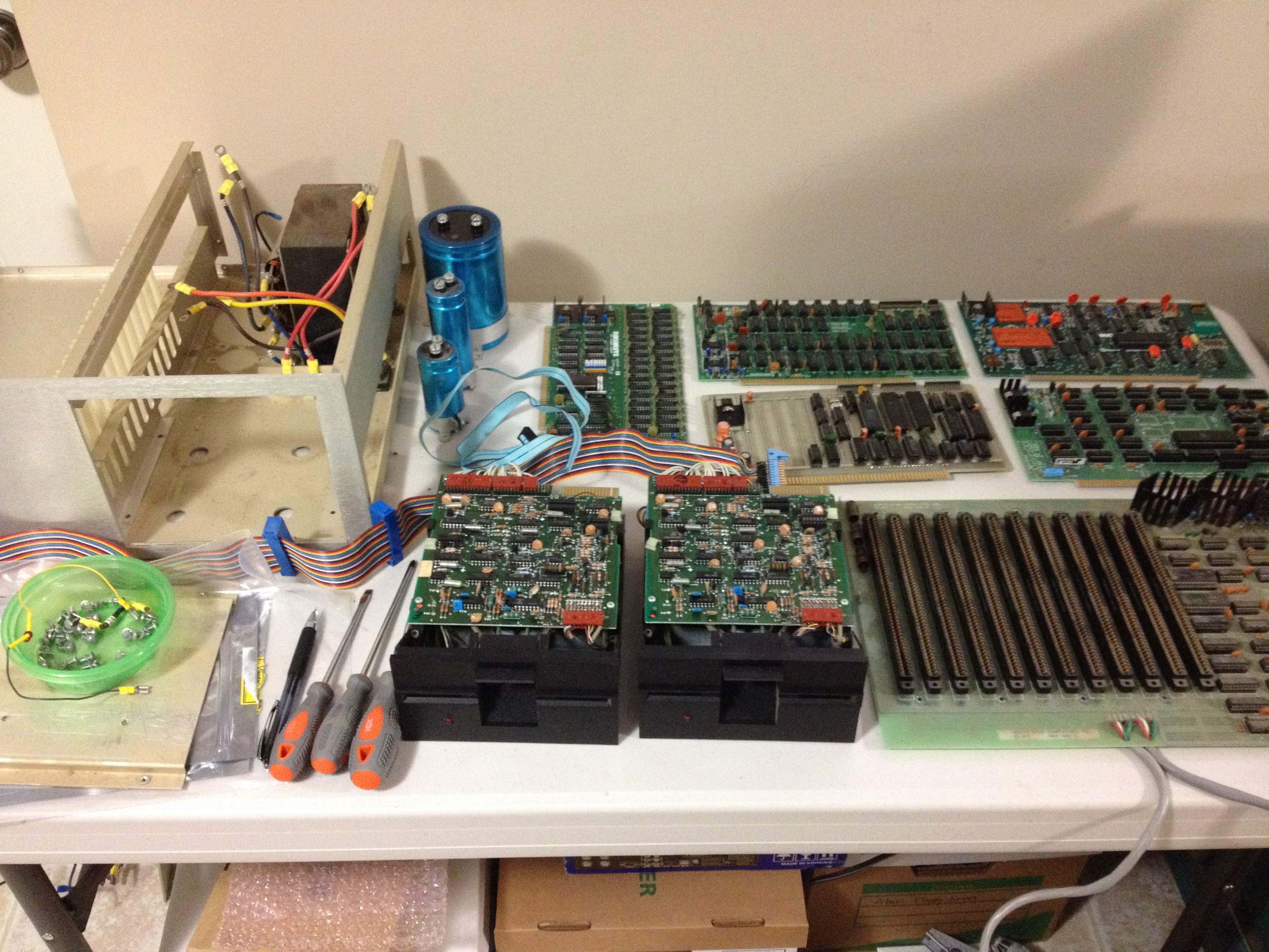
After re-assembling the motherboard inside the cassis and hooking up the power supply, it was time to check the power rails and make sure everything was working.

I threw the switch and the power supply came to life. I probed the power supply voltages as they arrived at the motherboard and everything looked fine. However, when I checked for power at the backplane sockets themselves, I discovered that the -18v rail was missing from about half of the sockets.

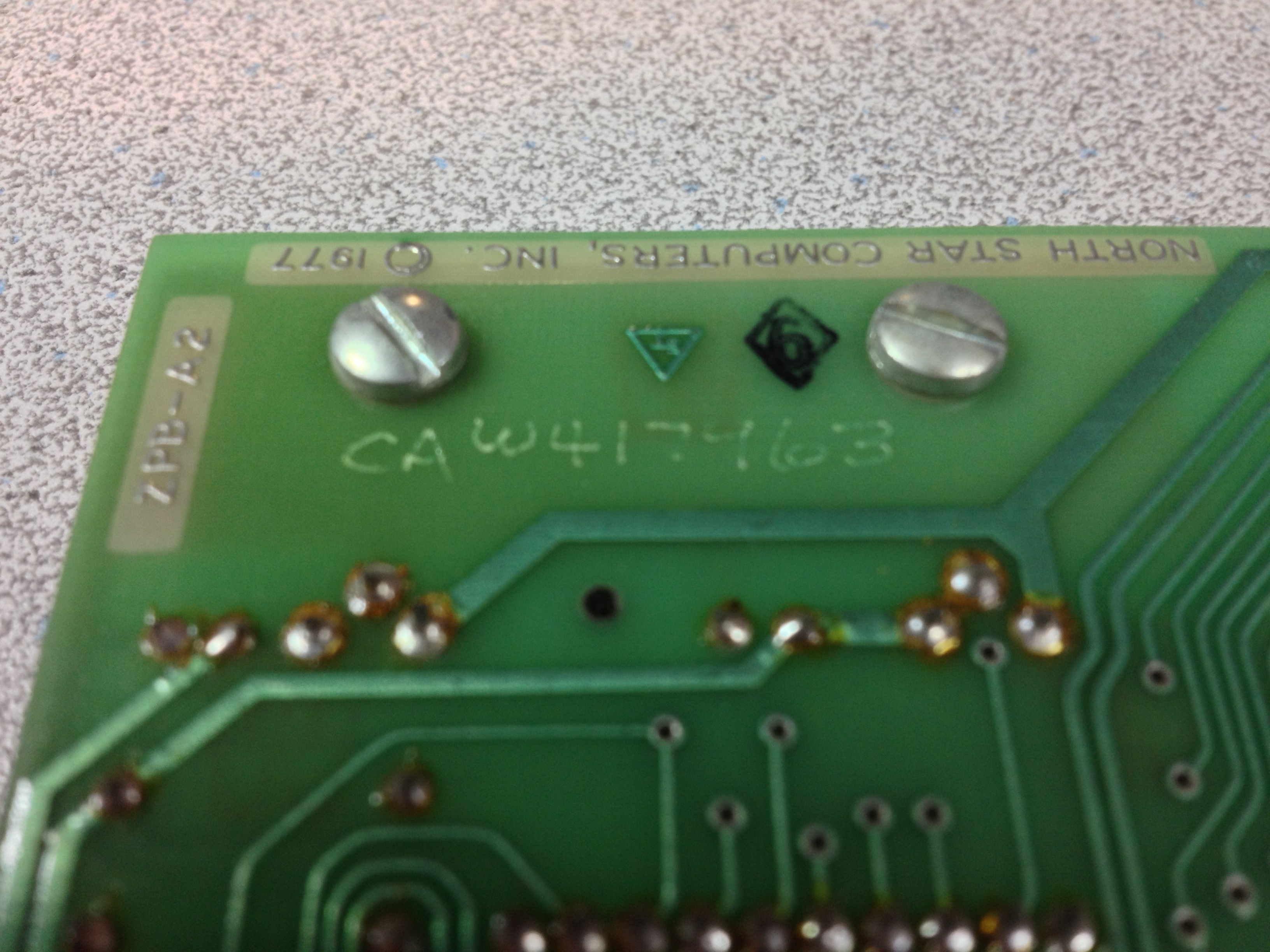
Because the rail was there for half the sockets and not there for the other sockets, it must be a fault on the motherboard.  Several dozen screws later (actually, only 8, but it feels like more), I pulled the motherboard out and did a visual inspection of the underside traces.

IMG_2894
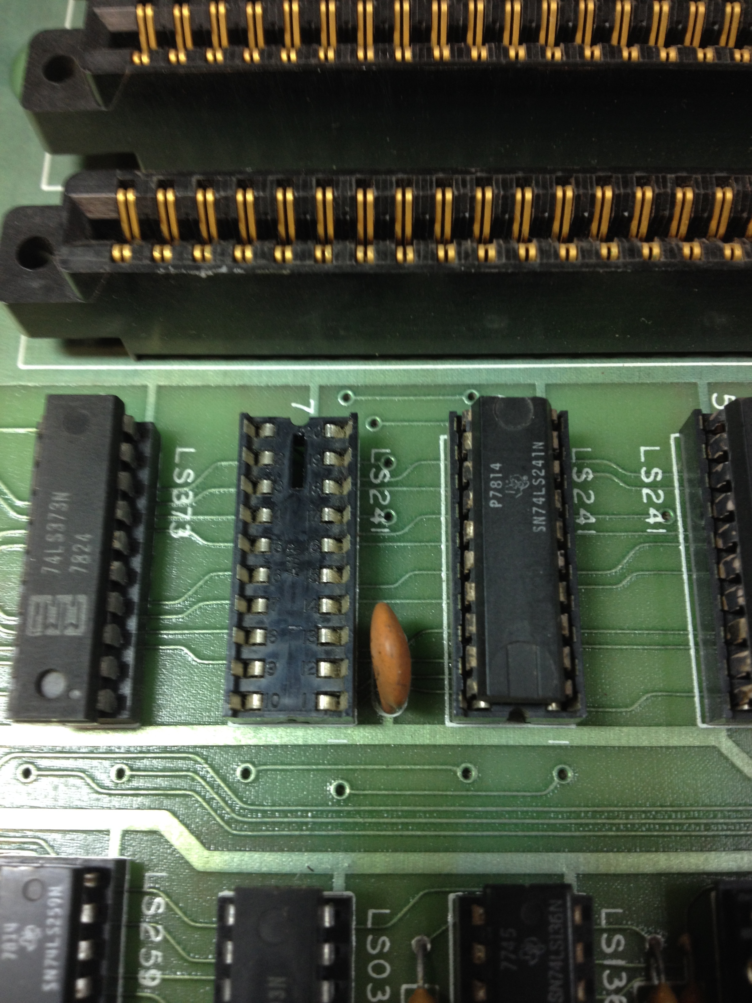
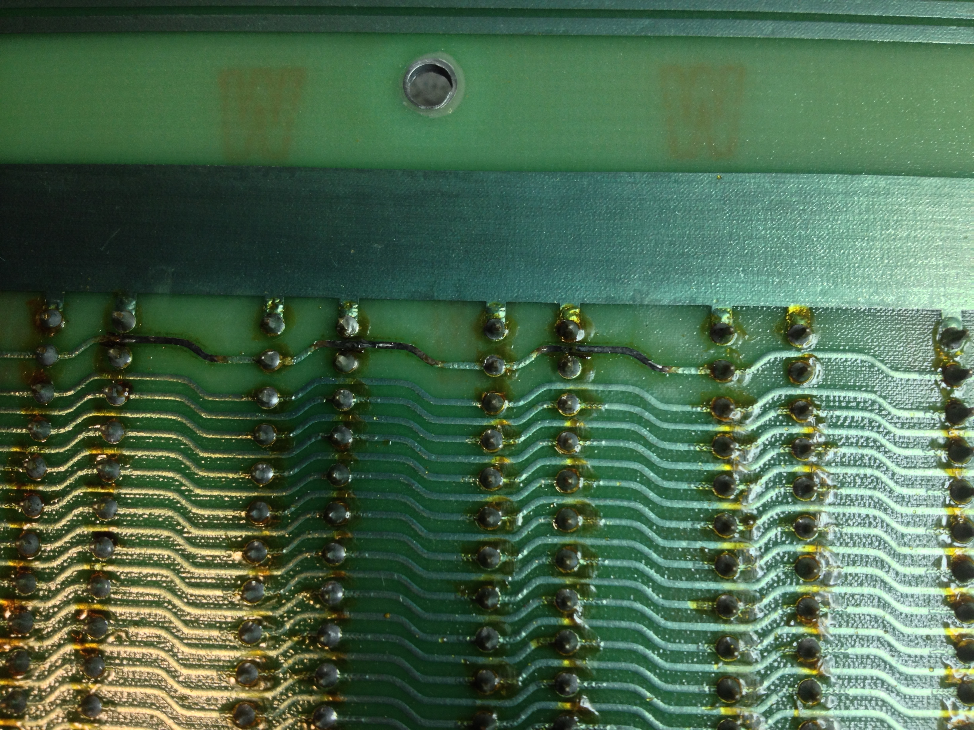
I’m not sure how I missed it when I was cleaning the board, but this time it was obvious – a burned out trace. There’s a serious design flaw in the NorthStar Horizon – the power rails from the linear power supply go straight to the backplane without any in-line fuses. Later S-100 machines have fuses on the backplane which would have protected the motherboard. If this was my machine 30 years ago, I probably would have retrofitted some fuses, but this machine has gone from a functional tool to a museum curiosity, so now isn’t the time to start making modifications.

IMG_2897
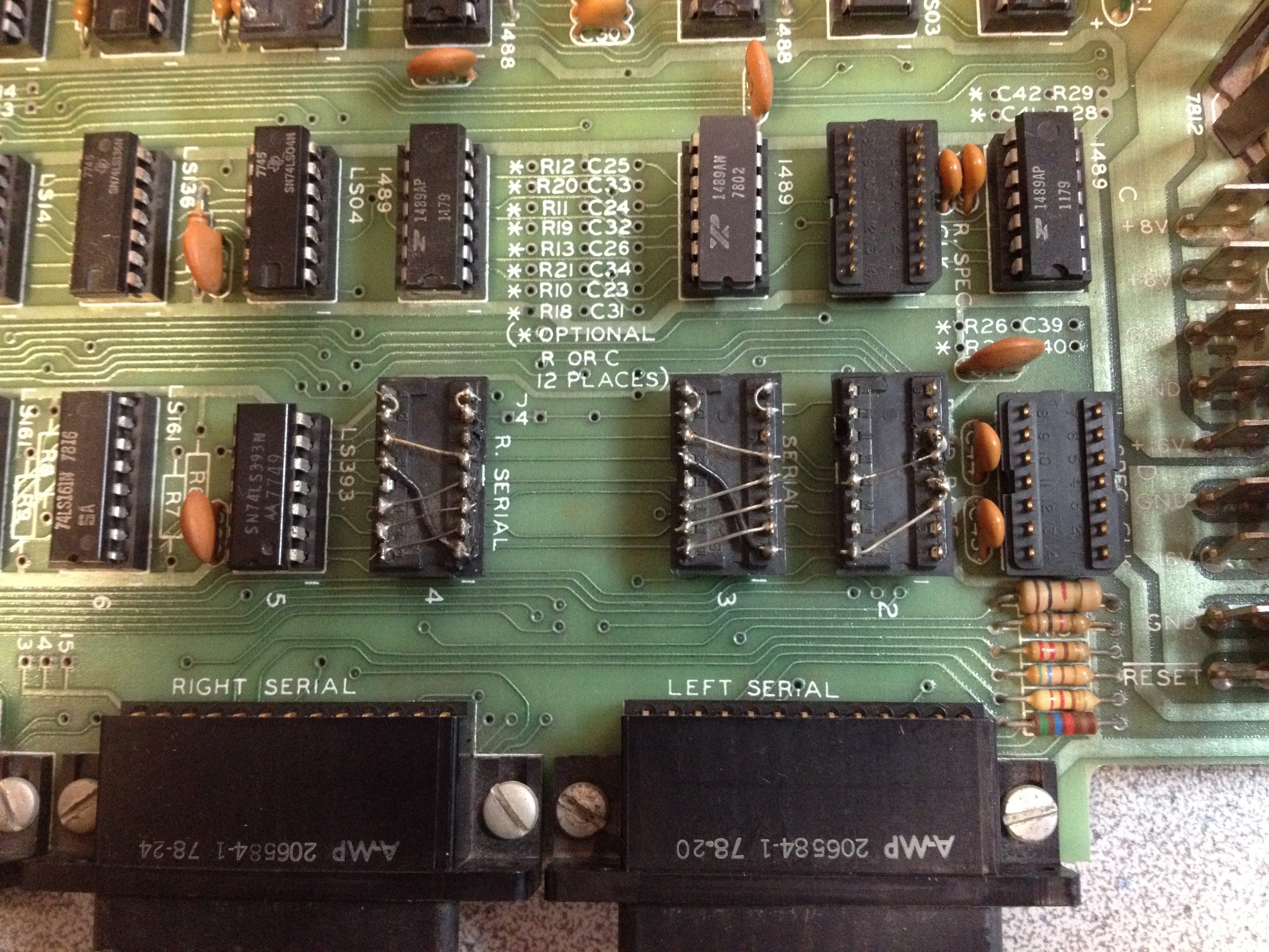
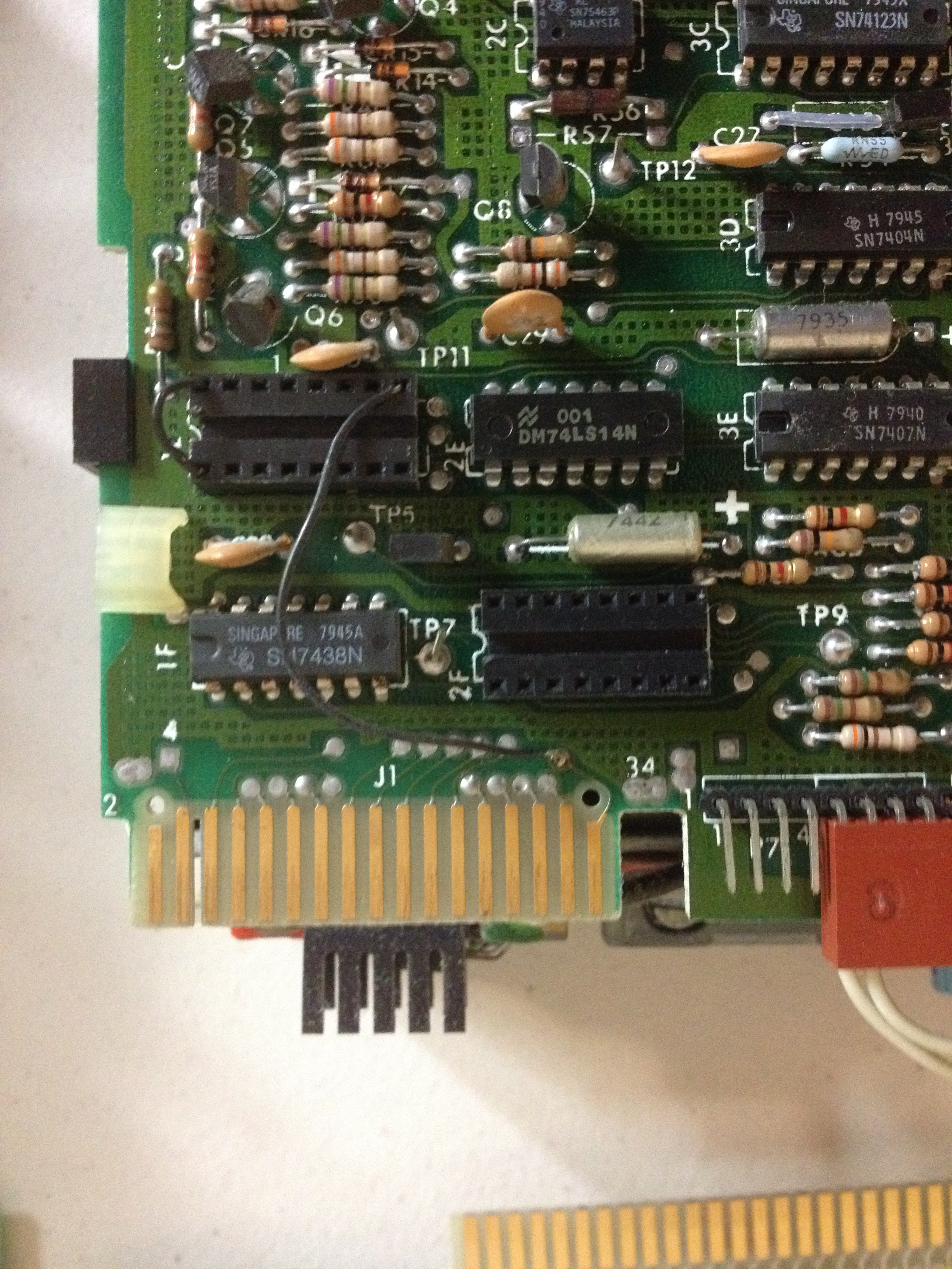
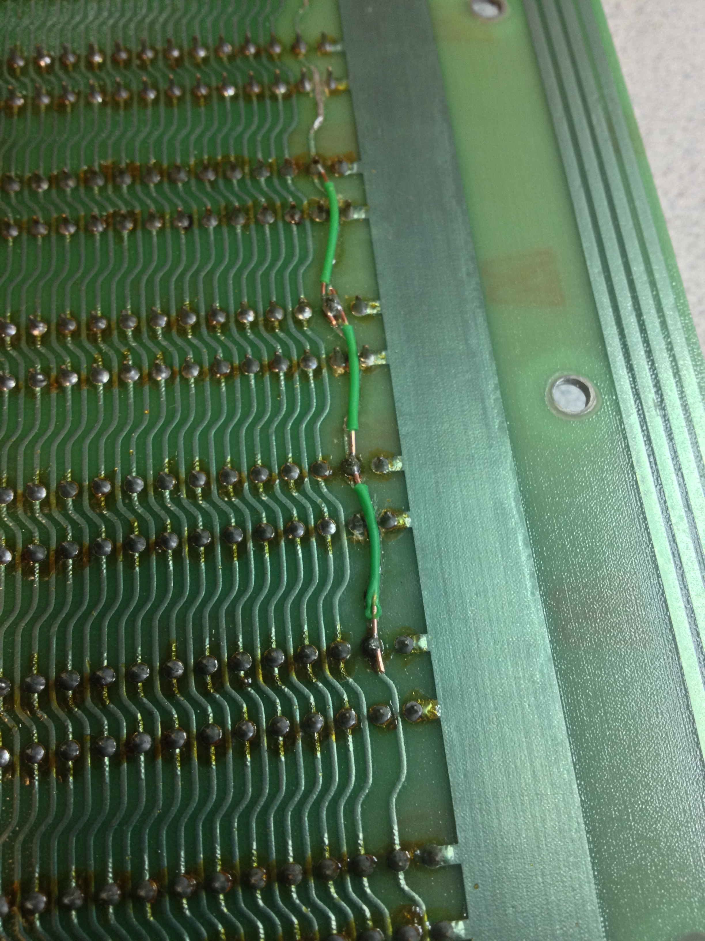
I identified three areas in the trace that had burned through, and carefully scraped away the destroyed trace. The trace winds its way between connector pins, so I used a small piece of insulated wire to re-connect the trace.

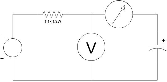
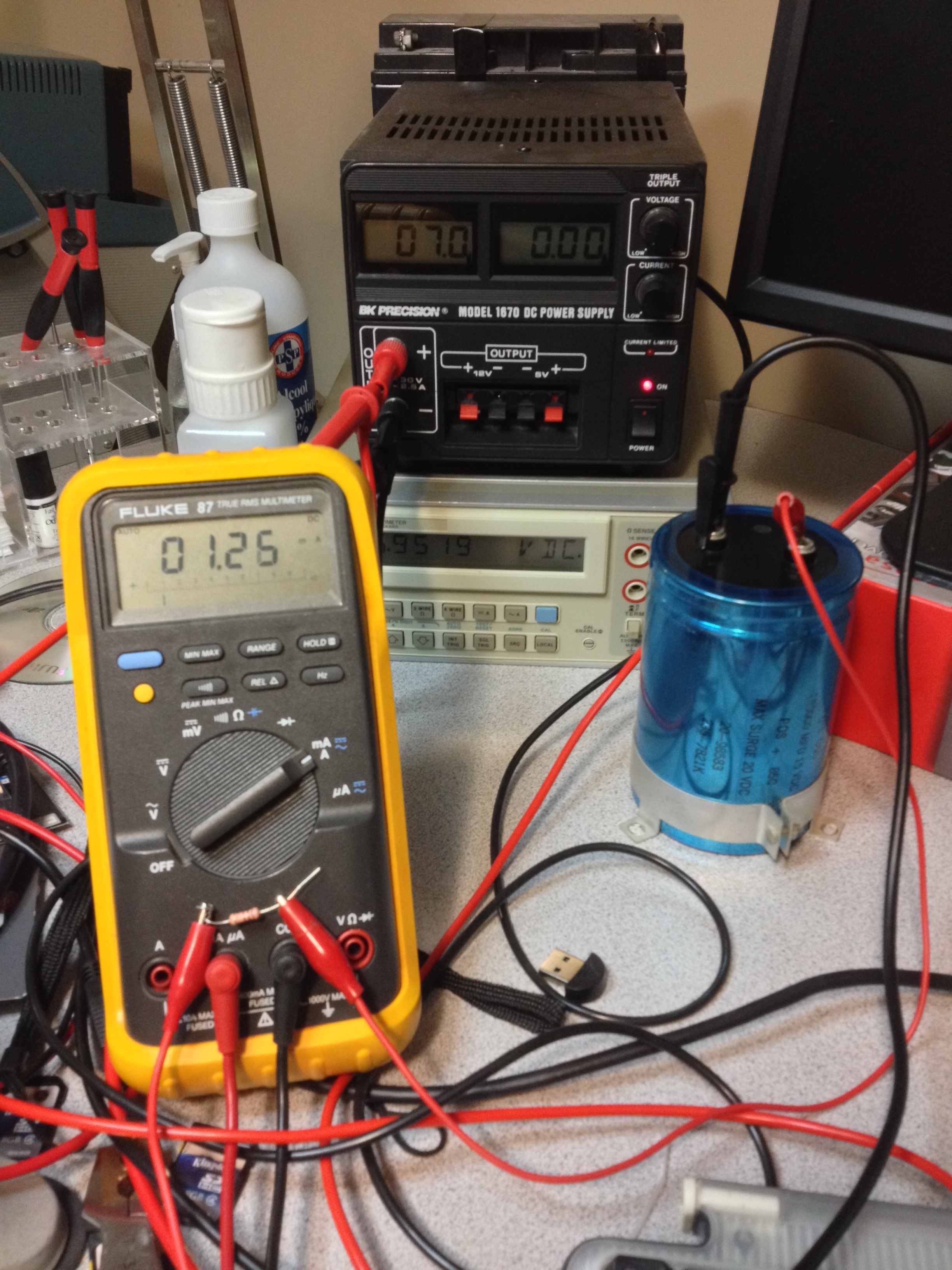
A quick test with my multimeter made sure that the trace was reconnected and there weren’t any shorts to adjacent pins. I reinstalled the motherboard with it’s several dozen screws, and re-connected the power supply. This time, all the voltage rails were now visible at all the connectors.

I am now ready to start plugging in boards and getting the old beast to show some signs of life.

Power Supply

IMG_2865After reconditioning the capacitors and cleaning out the chassis, I continued working on the power supply. There’s actually very few components, so it was pretty easy to check.  The bridge rectifier and two rectifier diodes were a simple matter of testing with a multimeter.  The transformer was tested for open or shorted windings.  After cleaning and re-assembling the back panel, I noticed that the fuse holder wasn’t closing correctly.  A quick examination showed that one of the metal fuse contacts was broken. A quick rummage around my junk pile found a suitably aged replacement.

IMG_2882I reinstalled the capacitors and it was time to apply power.  No smoke! All three power rails came up beautifully. The fan – an item I was sure would need replacing – is remarkably quiet and smooth running.

The icing on the cake for this part of the project was getting the front panel LED mounted correctly. The original plastic clip that held the LED in place was broken. Fortunately, I had some very similar LED clips in my parts bin, so with a little bit of gentle persuasion I was able to get the new clip installed.IMG_2886 I’m suspecting that over the period of 36 years, the industry standard sizing for LED packages may have become ‘metrificated’ (I know it’s not a word, but I’m owning it) so it was a little bit of a tight squeeze, but it’s in there and it looks beautiful.

Motherboard

The NorthStar Horizon is unique among S-100 machines because the motherboard is more than a passive backplane.  The Horizon’s motherboard contains circuitry for two serial ports and two parallel ports (one in, one out).  There are voltage regulators on the motherboard that supply power to the serial and parallel circuitry, and they also provide the power for the two floppy drives.

IMG_2869My motherboard had the same corroded IC pin issue that I found with the CPU board.  A quick brush with a glass pen took care of that.  While taking great care to make sure each IC was put back in the correct socket with the correct orientation, I discovered that the original builder had inserted a socket in backwards.  Trying to de-solder the socket and put it in the right way round could potentially cause damage to the board, and with an IC in the socket, the incorrect orientation isn’t noticeable.

While the motherboard is out of the machine, I took the time to note the jumper settings for the serial ports – knowing the serial configuration will certainly be useful when it comes time to talking to the machine 🙂  The first serial port is configured for 9600 baud, and the second serial port is configured for 1200 baud.

IMG_2884These values seem like a reasonable place to start, so I’ll leave them alone.

Next, the capacitors needed testing.  There are three 6.8μF tantalum capacitors on-board.  All of them measured within tolerance.  The ESR (equivalent series resistance) seemed a little high, but a quick search of Digikey shows ESR values for modern tantalum capacitors for this value ranging from 2 to 8 ohms.

Capacitor Value ESR
C3 6.9 μF 3.44 Ω
C7 7.7 μF 6.55 Ω
C10 7.3 μF 1.85 Ω

I then brought up each of the power rails with a current-limited supply to make sure there were no shorts.

Rail Input Rail Output Current Draw
+8v 5.00v 500mA
+16v 11.85v 80mA
-16v -11.49v 50mA

I now have to wait until I’ve reconstructed the linear supply in the chassis before I can re-install the motherboard. So far, everything is looking good.

CPU Board

IMG_2835The first board to tackle is the CPU board – part number ZPB-A2.  The CPU board, the motherboard, and the chassis all have a number engraved – “CA W417963”.

Tasks performed on this board:

  • Clean socketted IC pins with glass pen
  • Test electrolytic and tantalum capacitors
  • Clean edge connector
  • Install EPROM circuitry
  • Change boot address jumper block

IMG_2848The legs on the ICs were quite corroded on this board (see pictures). Each one was removed from its socket, and given a quick brush with a glass pen (like this).

Next, I tested each of the electrolytic and tantalum capacitors.  I used an ESR meter to check that the components were still within tolerance, as well as making sure that they had not developed any shorts.  All of the capacitors passed, so the next step was to power up the board with a current-limited supply and allow it to warm up.  The total draw on this board is 570mA.

IMG_2864To address the biggest problem with resurrecting a NorthStar Horizon – how to make a boot disk – I needed to install a boot monitor that will allow me to hand-enter (or machine-enter over the serial port) a program to write an image using the disk controller.  Following the instructions for the original CPU board, I populated the optional monitor ROM components.

The boot ROM lives at address EC00, so I had to adjust two sets of jumpers on the CPU board – the ROM base address, and the boot address.  By default, the CPU board boots to address EB00 (a small boot PROM on the disk controller), but we need to boot the monitor at EC00.  As you can see from the pictures, I’ve added headers to (hopefully) address the PROM and boot the right address.

Once the machine is complete and boot disks have been written, I can change the boot address back to EB00 to make the machine boot from floppy.

IMG_2858

Capacitor Reconditioning

The power supply in the NorthStar Horizon is a linear supply (common for the day), consisting of a transformer, rectifier, and capacitor.  The electrolytic capacitors in a linear supply are large, and the electrolyte inside the capacitor has a tendency to dry out as the capacitor ages.  It is important to test and condition old electrolytic capacitors before putting them back in to service, otherwise a catastrophic failure may occur, which could take out other components.

Capacitor ReconditionIn order to wake the capacitors from their sleep, and to test their effectiveness, I like to place a voltage across them (with a current-limiting resistor), and bring up the voltage over time to their maximum working voltage.  This process can help re-form the aluminum oxide layer in the capacitor.  At each step, the current should drop as the capacitor charges up.  Once the capacitor is charged, the current should be minimal.  If there is more than a couple of mA flowing, the capacitorIMG_2794 should be replaced.

In my case, the two smaller capacitors pass with flying colours.  The large capacitor is still leaking 0.96mA after 2 hours of conditioning at 15v.

Oh, and remember to discharge the capacitor after reconditioning it.  There’s a lot of joules stored in there!


Floppy Drive Strangeness

In my furious attempt to not do anything constructive until the Retro Challenge officially starts, I’ve completely disassembled the NorthStar Horizon to prepare everything for cleaning and testing.

IMG_2814During disassembly, I discovered that the floppy cable that runs from the floppy controller board goes to the two Tandon TM-100 floppy drives, then continues on and exits the back of the chassis and terminates in a dangling connector.  I can only assume that this was for additional floppy drives, but the cable harness is certainly not the original configuration for this machine.

IMG_2822I only ever intend to have this machine run with two floppy drives as it cam configured from the factory, so I will probably modify this cable to only have the two floppy connectors on it.

Neither of the internal floppy drives have a terminator resistor pack, so I will have to either purchase one, or make one up with 150 ohm resistors.

Next, I got in to checking the jumper settings for the floppy drives.  The first drive was jumpered as drive 3.  The second drive was different.  It had a long wire soldered on to edge connector pin 34 and ran over to pin 9 of the jumper configuration socket.  There were no jumpers in any of the drive select positions.

This puzzled me for a few days, until I happened to stumble upon a paragraph in the Horizon documentation:

  To program a drive as drive number 4 perform the following
  instructions on the printed circuit board mounted on top of
  the disk drive.

  a. Solder a jumper wire between pin 34 of edge connector J1
     and location 1F pin 6.  Take great care to connect the wire
     to the very tip of pin 34 so that the ribbon cable
     connector can slip as far onto J1 as possible.
  b. Solder a jumper wire between 1F pin 9 and 1F pin 11.
  c. The uninarked strap location between MX and MH at location
     1F is now the location for programming drive 4.  It can be
     labeled DS4.  This strap should remain connected and the
     straps labeled DS1, DS2, and DS3 should be disconnected.
     Be sure to disconnect this strap if the drive is ever
     programmed to be drive 1, 2, or 3.

IMG_2819

For some reason, the NorthStar Horizon puts DS4 on pin 34 instead of the more normal pin 6.  These drives were jumpered for drives 3 and 4.  I will need to change this back to drive 1 and 2 for my configuration.

Missing Pieces

The Retro Challenge is getting closer.  It’s tough not to just dive right in to the project, but I’ve got to wait until July 1.  In the meantime, I’m slowly putting together the missing pieces that I will need to get my Horizon up and running.

I have sourced some precious hard sectored floppy disks – an entire box of 10!  I have a tracking number, so these should be here soon.

Hayes Microcoupler

The other item I thought might be difficult to locate was a micro coupler for the Hayes Micromodem 100.  I found one on Ebay for a price less than the cost of shipping it to me!

I also ordered the components I need to add the boot PROM socket to the processor board.  Those arrived overnight from Digikey.

I’m not going to know if there are any other missing pieces until I start tearing the machine apart.  Soon…


Task List

The challenge doesn’t officially begin until July 1, but I thought it would be okay to survey what I have, and make a list of things that I will need to do in order to be successful.

As of right now, this is what I know needs to be done:

  • Inventory of cards. Identify the S-100 cards I have and acquire documentation on each (jumper settings, schematics, etc)
  • Disassemble. Although not too bad, there’s a bit of dust and dirt on the motherboard and power supply that needs to be cleaned up.
  • Recondition power supply. The large electrolytics in the power supply need to be reconditioned and tested.
  • Test capacitors on boards. Tantalum capacitors of this vintage have a tendency to build up internal whiskers that can cause shorts.
  • Logic test. Bring up the system and test for the correct operation of the logic. At this point, all I will have is a small boot PROM on the disk controller. There is a test sequence in the documentation for troubleshooting logic issues at this level.
  • Add boot PROM to CPU card. The CPU card has empty pads for a 2708 PROM (with decoding logic and power supply). I need to install this in order to boot to a ROM monitor. From here I will be able to do memory tests, and bootstrap software to be able to write boot disks.
  • Burn a 2708. This is turning out to be remarkably harder than I initially thought. The 2708 is an early EPROM that has unique voltage rail requirements for programming and operation. Most modern programmers can’t handle the 2708.
  • Acquire some blank DS/DD 10-sector hard sectored floppy disks. This will probably end up being the most difficult part of the whole project. Hard-sectored floppy disks dropped out of favour right around the time of the release of this machine, and haven’t been manufactured for many years.
  • Do something useful. Once the machine is up and running, I need to identify a task that I can use the machine for. I do have a Hayes Micromodem 100 card in here, so I may make use of that – however I’m missing the micro coupler which contains the analog interface circuitry to the phone line.

There you have it. Looks like I’m in for a busy 30 days!

Summer Retro Challenge 2014

Northstar HorizonAs it usually happens with me, I was watching a n old S-100 machine on Ebay, but missed the end of the auction.  To my surprise, it didn’t sell.  I decided to take a chance and email the seller to see if he was interested.  As luck would have it, the seller was interested, and the machine was only 370km away from me in Bellingham, WA (with only a minor wrinkle of an international border in between).

A 10 hour drive later (and an awkward conversation with an unbelieving border guard) I had in my possession a beautiful Northstar Horizon machine.

Kelowna to BellinghamThis is my first S-100 machine, but my third or fourth CP/M machine.  It needs a little TLC. The power supply and it’s huge electrolytic capacitors have to be brought up slowly.  The boards have to be checked for bad tantalum capacitors.  The small matter of creating a hard-sectored boot floppy awaits (the biggest road block to any new Northstar Horizon collector).

After years of watching on the sidelines, this year I’m going to enter the 2014 Summer Retro Challenge.  My entry is going to be getting this machine up and running, with the intent of doing something ‘useful’.  I reserve the right to re-define the word ‘useful’ as the competition advances!

A Blast From The Past

I was pawing through the latest issue of Circuit Cellar when I came across an article describing a new development kit from Zilog for their new eZ80acclaim! modules.

I remember playing with Z80 hardware and assembly programming 20 years ago! Before I knew what was happening, the credit card jumped out of my wallet and ordered one of the kits. $99 later, I had myself an eZ80F91 module, a development board, an in-circuit emulator, an ethernet switch, and all the cables I needed. Some manufacturers want to gouge you for their evaluation kits – not so here.

The kit comes with a full function C compiler and IDE. A few minutes after hooking up, I was compiling and loading the sample apps. Very easy to use. Who’d have thought – a Z80 with ethernet!